A guide to Differential Interference Contrast (DIC)
What is Differential Interference Contrast (DIC)?
Differential Interference Contrast (DIC) microscopy is an optical imaging technique used to enhance contrast in transparent or unstained specimens that are difficult to visualise using conventional brightfield microscopy. By converting small differences in optical path length into variations in image intensity, DIC produces high-resolution images with a characteristic pseudo three-dimensional appearance.
DIC microscopy is widely used in life science research, particularly for imaging living cells, tissue slices and other transparent biological samples without the need for staining. The technique provides excellent edge definition and contrast while preserving the full numerical aperture of the microscope, allowing fine structural details to be observed with high resolution.
One of the most common applications of DIC is in electrophysiology, where researchers use it to identify and target individual cells for patch clamp recording. When combined with infrared (IR) illumination, DIC is especially effective for imaging thick specimens such as acute brain slices, as longer-wavelength IR light penetrates deeper into tissue than visible light.
Although DIC can be used alongside fluorescence microscopy, the additional optical components may slightly reduce fluorescence signal intensity. In most applications, however, this reduction is minimal and does not significantly affect image quality.
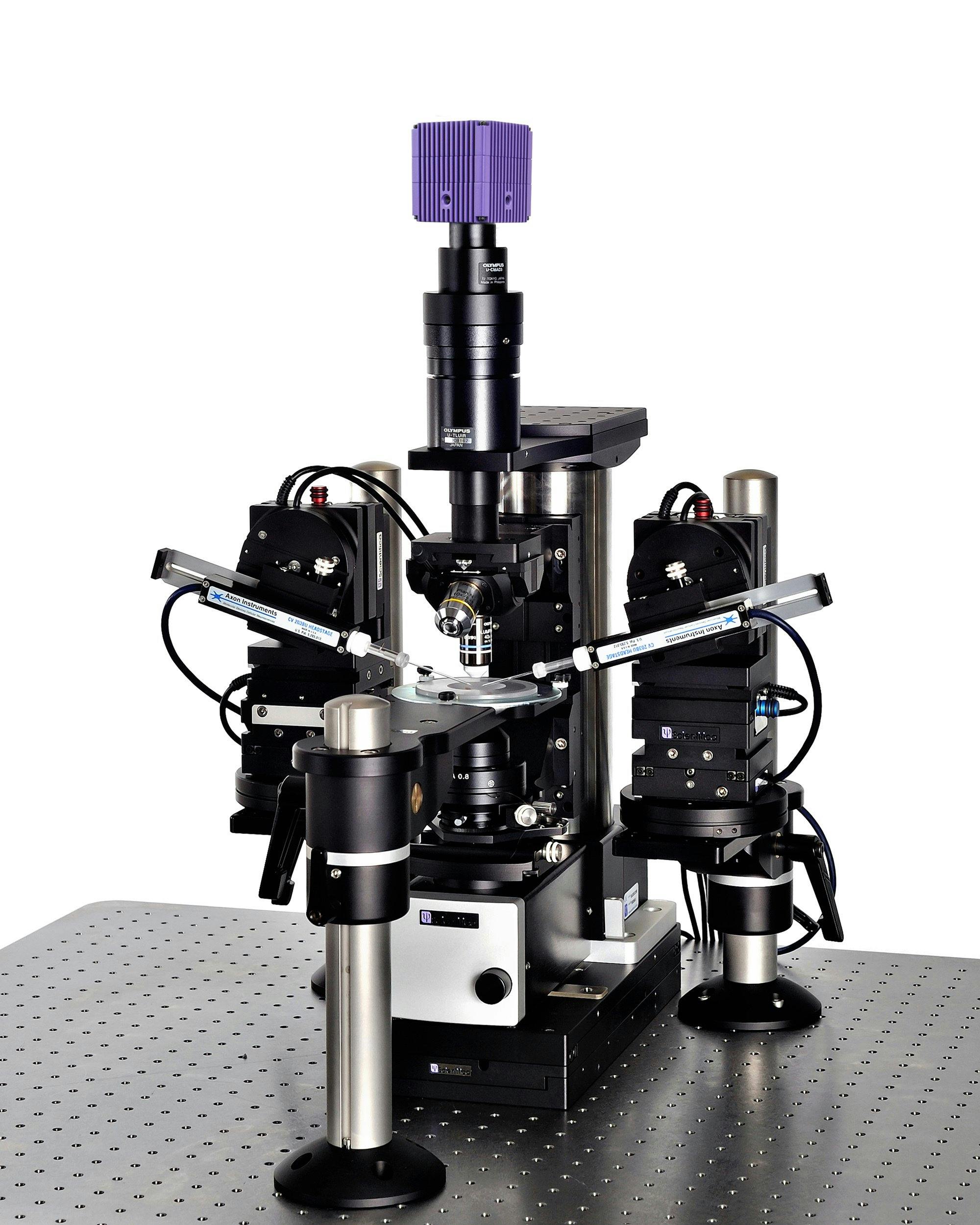
In this guide, we explain the principles behind Differential Interference Contrast microscopy, how DIC images are formed, and how to set up a DIC system on an upright microscope - like the Scientifica SliceScope.
When is DIC used?
Because DIC provides excellent contrast while maintaining the full numerical aperture of the microscope, it is often chosen when high-resolution imaging is required. The technique is particularly useful for imaging thick tissue samples, cultured cells, organoids and other specimens where subtle structural differences need to be clearly resolved.
Common applications of DIC microscopy include:
- Patch clamp electrophysiology
- Brain slice imaging
- Live-cell imaging
- Cell culture studies
- Developmental biology
- Embryology
- Imaging transparent organisms and tissues
- High-resolution imaging of unstained specimens
For many researchers, DIC remains one of the most versatile contrast techniques available, combining high image quality, excellent contrast and compatibility with living biological samples.
How does DIC microscopy work?
Differential Interference Contrast (DIC) microscopy enhances contrast by detecting small differences in a specimen's optical path length. These differences arise from variations in specimen thickness and refractive index, which alter the phase of transmitted light. DIC converts these otherwise invisible phase differences into changes in image intensity, allowing transparent structures to be visualised with high contrast and resolution.
To achieve this, DIC uses polarised light, specialised prisms and interference between two closely spaced light beams.
In DIC, light emitted from the source is linearly polarised by passing through a polariser. The linearly polarised beam of light enters an objective-specific prism, which splits it into two rays that vibrate perpendicular to each other. The rays are parallel as they pass through a condenser, but as they are vibrating perpendicular to each other, they are unable to cause interference.
The split beams pass through the specimen. The specimen’s varying thickness and refractive indices alter the wave paths of the beams. They then enter the objective, where they are focussed above the rear focal plane. The two beams enter a second prism, in the nosepiece, which combines them. Because the beams passed through different parts of the specimen, they have different lengths.
The analyser, which is a second polariser, brings the vibrations of the beams into the same plane and axis, causing destructive and constructive interference to occur between the two wavefronts. The light then travels to the eyepiece or camera, where a DIC image with differences in intensity and colour, can be seen.

A diagram showing the journey of light in DIC. The yellow lines represent non-polarised light, whilst red lines represent polarised light.
Why do DIC images appear three-dimensional?
A characteristic feature of DIC microscopy is its pseudo three-dimensional appearance. The interference process creates bright and dark gradients along specimen edges, producing an effect similar to directional illumination.
Although DIC images often appear to have depth, this is an optical contrast effect rather than a true three-dimensional representation of the specimen. Nevertheless, the enhanced edge definition and contrast make DIC particularly useful for visualising transparent cells, tissue structures and unstained biological samples.
The resulting images combine high resolution, excellent contrast and minimal optical artefacts, making DIC one of the most widely used contrast techniques in biological microscopy.
Advantages of DIC microscopy
High Contrast Without Staining
DIC enhances subtle differences in refractive index and specimen thickness, allowing transparent or unstained samples to be visualised with excellent contrast. This makes the technique particularly valuable for observing living specimens in their natural state.
High Resolution Imaging
Unlike phase contrast microscopy, DIC uses the full numerical aperture of the microscope objective and condenser. As a result, image resolution is maintained, allowing fine structural details to be observed more clearly.
No Halo Artefacts
Phase contrast images are often affected by halo artefacts that can obscure specimen boundaries and reduce image quality. DIC produces crisp images with well-defined edges and is largely free from these artefacts.
Suitable for Thick Tissue Samples
DIC is commonly used with infrared (IR) illumination, which penetrates deeper into biological tissue than visible light. This makes the technique particularly effective for imaging thick specimens such as acute brain slices used in electrophysiology experiments.
Ideal for Live-Cell Imaging
Because DIC does not require fixation or staining, it is well suited to time-lapse imaging and studies of dynamic cellular processes. Researchers can observe living cells over extended periods while minimising sample preparation.
Excellent for Electrophysiology Applications
The high contrast and apparent three-dimensional appearance of DIC images make it easier to identify individual cells and tissue structures. For this reason, DIC is widely used in patch clamp electrophysiology to target neurons and other cells for recording.
Limitations of DIC
Higher Cost and Complexity
DIC requires specialised optical components, including polarising filters and Nomarski or Wollaston prisms. These additional components increase system cost and make setup more complex than standard brightfield microscopy.
Precise Alignment Is Required
To achieve optimal image quality, DIC components must be carefully aligned. Incorrect alignment can reduce contrast, introduce image artefacts or prevent interference from occurring correctly.
Contrast Depends on Specimen Orientation
The contrast generated by DIC is directional. Structures aligned parallel to the shear direction may appear with lower contrast than structures oriented perpendicular to it. As a result, some features may become more or less visible depending on specimen orientation.
Pseudo Three-Dimensional Appearance Can Be Misleading
While the characteristic shadowed appearance of DIC images can make structures easier to visualise, it does not represent true topography. Researchers should be aware that apparent height differences may be optical artefacts rather than actual three-dimensional features.
Reduced Compatibility with Some Fluorescence Applications
DIC can be combined with fluorescence microscopy, but the additional optical elements may slightly reduce fluorescence signal intensity. In most cases this effect is minor, but it may be important when imaging very weak fluorescent signals.
Not Suitable for All Specimens
DIC performs best on transparent specimens that introduce phase differences into transmitted light. Highly absorbing, strongly scattering or opaque samples may be better imaged using alternative microscopy techniques.
Components required for DIC microscopy
DIC microscope requires several specialised optical components in addition to a standard transmitted light microscope:
- A polariser
- An analyser
- A condenser prism
- An objective prism
- An appropriate illumination source
The exact configuration varies between microscope manufacturers and objective magnifications, but the underlying setup principles remain the same. The example below demonstrates how DIC is configured on a Scientifica SliceScope.
How to setup to DIC
Before setting up DIC on a microscope, ensure all components are free of dust and debris, as dirty objective, condenser and lens elements can reduce image quality.

1. If using a white light source, insert an infrared bandpass filter into the slider on the SliceScope filter wheel and secure in place with a locking screw, this ensures only infrared light passes through to the polariser. If using an IR-LED, a bandpass filter is not needed.
2. Insert the polariser into the silver-plated section of the filter wheel, underneath the condenser, shown in the image below. The polariser is on a rotatable mount, enabling it to be rotated when aligning DIC.
3. Ensure your condenser does not have a protective covering on it, as this will obscure images produced using DIC.

The polariser inserted in the filter wheel
3. Ensure your condenser does not have a protective covering on it, as this will obscure images produced using DIC.
4. Keeping the condenser facing upwards, use a hex key to unscrew the two screws either side of the condenser to open it up. Turn the top section only upside down.
5. Loosen the grub screw on the side of the condenser and remove the spacer ring from the top half, as this is not needed. Insert the objective-specific prism, lining up the metal pin on the prism with the slot in the condenser. Tighten the grub screw and put the condenser back together. Each objective requires a different objective-specific prism, based on the magnification of the objective, for example a 40x objective requires a WI-DIC40HR objective specific prism. Usually, a prism is only required for the high magnification objective you are using.

The left image shows the WI-DIC60HR prism in the condenser. On the right is the condenser setup on the SliceScope with the filter wheel below.
6. The second DIC prism (WI-DICT or WI-DICTHRA) is in a fixed mount which is inserted into the nosepiece above the objective. Loosen the grub screw on the right-hand side of the nosepiece arm and slide the nosepiece (WI-SRE) forward. Insert the second DIC prism into the nosepiece and secure it using the small screw at the rear-right corner of the nosepiece.
If using a MOC, pictured below, loosen the four screws to open it and then follow the instructions above.

The image on the left shows the objective prism in the MOC. The image on the right is the nosepiece, where the objective prism is located.
7. If fluorescence is being used, insert the analyser (U-AN) into the fluorescence turret, as shown below. If fluorescence isn’t being used, insert the analyser (U-ANT) into the U-KPA.
8. The U-KPA can then be secured on the SliceScope under the imaging lens or trinocular head.
9. The polariser and analyser need to be aligned so that their transmission pathways cross at a 90 degree angle to one another. This can be achieved by rotating the polariser in the filter wheel. As this can be rotated 360 degrees, the analyser and U-KPA can be mounted in any orientation.

The image on the left is a U-AN analyser, and the image on the right shows the U-AN analyser inserted into a fluorescent turret on the SliceScope.
10. For DIC microscopy to be performed, Koehler illumination must be first set-up. Read our 6 step guide to Koehler illumination to help you set this up.
11. Once Koehler illumination has been set-up, DIC will need to be aligned
Aligning Differential Interference Contrast
1. Focus on a blank sample plate using either a 4x or 10x objective.
2. Move the DIC slider with the U-AN analyser into the light path. The U-ANT is not on a slider and is in a fixed position which is always in the light path.
3. If using a trinocular head, remove one eyepiece and view the sample directly down the trinocular head.
4. (a) When using eyepieces: rotate the polariser until there is a dark stripe through the centre of the field of view. This indicates that the polariser and analyser are aligned at 90 degrees to each other. (b) When using a camera: rotate polariser until the image is at its darkest.
5. If the condenser and objectives were removed, put them back at this point. Double-check that your condenser is still set-up for Koehler illumination.
6. Use your DIC objective to bring your sample into focus.
7. Add a specimen so that contrast can be optimised for the sample you are viewing.
8. As the SliceScope uses de Sénarmont DIC, a quarter waveplate is required, shown in the image below. The quarter waveplate introduces a bias retardation. Adjusting this changes whether structures appear concave or convex. Unscrew the locking knob and adjust the quarter wave plate as desired.
9. Lock the quarter waveplate in position using the locking knob.

Zoomed in section of the SliceScope with DIC components labelled
10. The lever in the image above controls the condenser iris aperture. If using eyepieces, remove one eyepiece and look down so you can see the internal condenser iris. Adjust the lever until the condenser iris just disappears from the field of view. When using a camera, adjust the lever until the image is at its sharpest.
11. DIC is a function of specimen orientation. Therefore, rotating the sample can improve or change the contrast of the image.
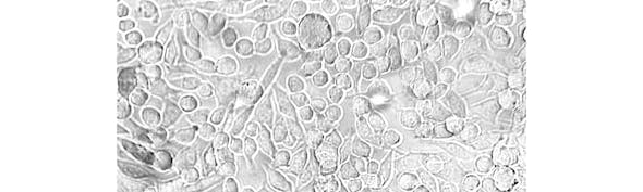
You should now have a clear DIC image! An example of a DIC image is below; the image has good contrast and the C.elegan has a 3D effect.

An adult Caenorhabditis elegans nematode imaged using DIC by Bob Goldstein
Learn about other contrast techniques
Scientifica SliceScope Systems
Scientifica SliceScope Pro 1000
An integrated electrophysiology system for patch clamp recording. The versatility of the system means that you can perform slice electrophysiology, fluorescent imaging, and in vivo experiments.
Scientifica SliceScope Pro 2000
The SliceScope Pro 2000 is an integrated electrophysiology system for patch clamp recording incorporating a large mounting stage. The versatility of the system means that you can perform slice electrophysiology, fluorescent imaging, and optogenetics.

Scientifica SliceScope Pro 3000
A static microscope system designed for in vitro electrophysiology experiments and capable of accommodating advanced imaging, such as two-photon and confocal.