What is Dodt Gradient Contrast?
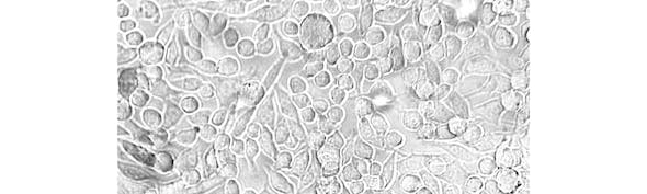
Dodt Gradient Contrast (DGC) is a transmitted-light microscopy technique developed to improve the visibility of unstained biological specimens. It is particularly valuable for neuroscience and electrophysiology applications, where researchers need to visualise neurons within thick living tissue slices.
Like other contrast-enhancing microscopy techniques, Dodt contrast converts otherwise subtle optical differences within a specimen into visible image contrast. However, unlike Differential Interference Contrast (DIC), Dodt does not require specialised objectives, prisms or polarisation optics. Instead, contrast is generated using a quarter-annulus aperture and diffuser arrangement that introduces a controlled illumination gradient across the sample.
The technique was developed during the 1990s by Professor Hans-Ulrich Dodt and colleagues at the Max Planck Institute of Psychiatry in Munich as an alternative to DIC microscopy for imaging thick biological specimens. By creating an asymmetric illumination profile, Dodt contrast enhances the visibility of cellular structures deep within tissue while maintaining a relatively simple optical setup.
Today, Dodt Gradient Contrast is widely used in neuroscience laboratories for visualising neurons in acute brain slices, particularly during patch-clamp electrophysiology experiments. It is also commonly combined with infrared illumination, allowing researchers to identify and target cells within living tissue preparations where conventional brightfield microscopy provides insufficient contrast. Infrared illumination reduces scattering in thick tissue and allows structures deeper within the specimen to be visualised more effectively.
In this guide, we explain the principles behind Dodt Gradient Contrast, the components required to generate the effect, and how to optimise the system for the best image quality.
When should I use Dodt Gradient Contrast?
Dodt Gradient Contrast is most effective when imaging thick, unstained biological specimens where conventional brightfield microscopy provides limited visibility.
Typical applications include:
- Acute brain slice imaging
- Patch-clamp electrophysiology
- Infrared transmitted-light microscopy
- Thick tissue preparations
- Live tissue imaging
While Differential Interference Contrast (DIC) often provides superior visualisation of fine cellular morphology, Dodt can offer excellent contrast in thick tissue without the additional complexity and cost of DIC optics. For this reason, it has become a popular choice for electrophysiology systems and neuroscience imaging workflows.
How Dodt Gradient Contrast works?
In DGC, a gradient contrast tube is placed between the light source and the condenser. Within the tube, there is a lens that focuses the light towards a diffuser positioned a short distance after a quarter annulus. The annulus blocks some of the light, and the diffuser creates a gradient of illumination. A second lens then collimates this light before it enters the condenser (see figure 1). The resulting illumination gradient converts phase-related optical variations within the specimen into intensity differences that can be detected by the imaging system.

Figure 1: The light path through a gradient contrast tube.
This method allows some light to illuminate the entire area initially lit by the light cylinder, making the image comparable to the actual object and reducing optical artefacts.
Because much of the light is blocked, DGC generates less stray light at the sample, enabling the use of a 1.4 numerical aperture (N.A.) oil condenser. Additionally, the curved slit of the quarter annulus means that the gradient of illumination occurs in two perpendicular directions. This feature becomes advantageous when attempting to visualise the dendritic branches of neurons travelling in various directions.
Setting up DGC
The only additional components required to make a brightfield microscope into a microscope capable of DGC are the gradient contrast tube itself and potentially a high-intensity infrared light source. The tube is placed between the transmitted light source and the transmitted illumination port of the microscope.

Figure 2: The Scientifica Gradient Contrast Tube
After installing the contrast tube, the first thing to do is to set up Koehler illumination on the microscope. Additionally, if your microscope has an additional diffuser between the illumination port and the condenser this must be removed, as it will dilute and disperse the contrast output provided by the spatial filter.

Figure 3: Schematic diagram of an upright microscope set up with DGC
Once the Gradient Contrast Tube is installed and the microscope is properly set up for Koehler illumination, the microscope can be optimised for Dodt Contrast (See figure 3 for schematic diagram of an upright microscope set up for DGC). The spatial filter adjustment ring (A) can be rotated to adjust the position of the quarter annulus by approximately 90 degrees enabling you to change the direction of the gradient across the sample. Finding the best placement for ring A will depend on your sample and is best optimised by trial and error. The direction of the gradient will highlight structures running anti-parallel to the spatial filter.
The diffuser position adjuster (B) can be rotated to move the diffuser axially along the light path (closer or further from the microscope) to alter the amount of contrast on the image by increasing or decreasing the sharpness of the gradient.
As an example, Figure 4 shows starch granules obtained from potato starch (Solanum tuberosum) observed without a Dodt contrast tube. The starch granules appear to be smooth objects without much definition beyond the outline.

Figure 4: Starch granules visualised without employing the Dodt contrast tube. Inset: zoomed version of the starch granule.
However, with the insertion of the gradient contrast tube, the growth rings (or lamellae) can be observed thanks to the increased contrast (Figure 5).

Figure 5: Starch granules visualised with the DODT contrast tube enabling the clear observation of the growth rings. The spatial filter is rotated 18 degrees between each image to outline the different features of the sample.
By rotating the quarter annulus using ring A, it is possible to see the outline of the growth rings in their different positions as they are radially oriented. These layers accumulate around the hilum, which is the granule’s point of botanical origin.

Figure 6: Starch granules visualised with Dodt contrast with diffuser closer to the microscope (left panel) and closer to the light source (right panel). The arrow indicates the hilum.
Adjusting the position of the diffuser with ring B alters the amount of contrast on the image (Figure 6). In the right panel of Figure 6, the position of the diffuser closer to the light source enables the observation of the hilum as a slightly depressed zone (purple arrow).
If after adjusting the spatial filter and diffuser you are still unable to obtain a clear image, a further method that can be employed to enhance the contrast is to laterally offset the condenser and bring the shadowed edge of the iris into the field of view to create additional oblique illumination within the light path (do not move the condenser axially). This will cast a gradient of light across your field of view (from darker to lighter), which you can adjust by altering the light source intensity. This process should enable you to obtain an enhanced contrast image in the centre of your field of view.
Please note that the Scientifica gradient contrast tube can be installed without any particular radial orientation. Therefore, the absolute position of the spatial filter will change depending on the alignment of the tube when affixed to the microscope. Additionally, the optimum position of Rings A and B will depend on the experimental sample.
Advantages of Dodt Gradient Contrast
As shown in Figures 5 and 6, DGC can produce images with a pseudo-relief appearance similar to DIC while requiring fewer specialised optical components. The technique makes unstained living tissue visible in a useful way without harming it.
DGC is a cost-effective contrast method that does not require the purchase of expensive optical elements. Additionally, no further elements are added into the light path between the sample and camera or detector, making it an ideal contrast technique for patching in combination with two-photon excitation fluorescence microscopy.
With a good camera, the fast frame rates available with this approach also make it an excellent tool for positioning micropipettes during patch clamp experiments to enable patch-clamp electrophysiology in thick brain slices (<300 µm).
Limitations of Dodt Gradient Contrast
The amount of light lost through the quarter annulus is significant. This can lead to darker images and may limit contrast if insufficient illumination reaches the specimen. For this reason, Dodt systems typically benefit from high-intensity light sources and sensitive detectors.
DGC is not as simple to align and set up as some other contrast techniques, and the need to readjust the settings regularly can be an annoyance for some users
Dodt vs DIC Comparison
The table shows a comparison of the Dodt Gradient vs Differential Interference Contrast (DIC)

Applications of DGC
The primary use of DGC is to visualise unstained neurons, which are mainly phase objects i.e. they alter the phase of the light waves that pass through them but not their amplitude. DGC is particularly useful when attempting to observe neurons in thick brain slices.
DGC is also ideal for performing patch-clamp experiments when used in combination with two-photon illumination as there is no requirement to have any optics between the collection module placed after the objective lens.
Conclusion
Dodt Gradient Contrast has become a widely adopted technique for imaging neurons in acute brain slices and other thick biological specimens. Its compatibility with standard microscope optics, combined with excellent performance in transmitted infrared illumination, makes it particularly well suited to patch-clamp electrophysiology and live tissue imaging. Although it requires careful alignment and optimisation, DGC can provide high-quality contrast in thick living tissue without the expense and complexity of DIC systems.
Learn about other contrast techniques
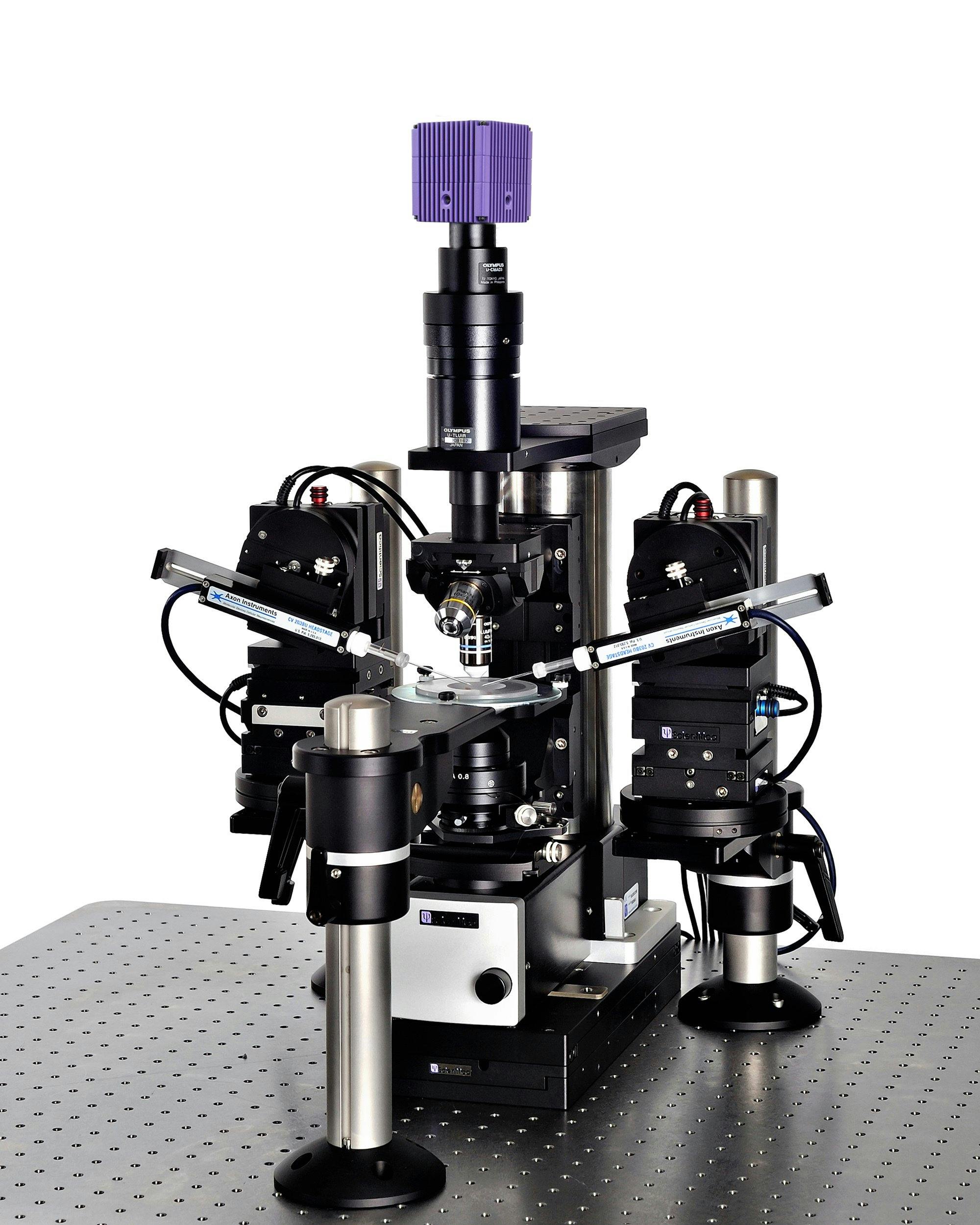
Scientifica SliceScope Pro 1000
An integrated electrophysiology system for patch clamp recording. The versatility of the system means that you can perform slice electrophysiology, fluorescent imaging, and in vivo experiments.
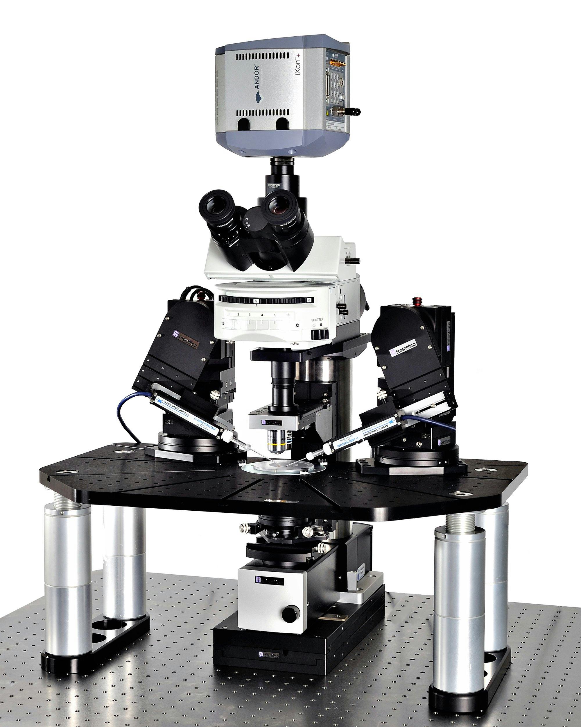
Scientifica SliceScope Pro 2000
The SliceScope Pro 2000 is an integrated electrophysiology system for patch clamp recording incorporating a large mounting stage. The versatility of the system means that you can perform slice electrophysiology, fluorescent imaging, and optogenetics.

Scientifica SliceScope Pro 3000
A static microscope system designed for in vitro electrophysiology experiments and capable of accommodating advanced imaging, such as two-photon and confocal.