Introduction to Oblique Contrast
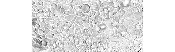
Oblique contrast (also known as oblique illumination microscopy) is a microscopy technique used to improve the visibility of thin, transparent, unstained specimens that can be difficult to visualise using conventional brightfield microscopy. By increasing image contrast without the need for staining, it provides a simple and cost-effective way to reveal cellular and tissue structures in live or fixed samples.
Like Differential Interference Contrast (DIC), oblique contrast produces images with light and shadow effects that give a pseudo three-dimensional appearance. This effect is created by illuminating the specimen from an oblique angle rather than directly along the optical axis. The resulting phase differences enhance subtle features within transparent samples, making them easier to distinguish than with standard brightfield illumination.
Applications using Oblique Contrast
- Live cell imaging
- Brain slice electrophysiology
- Patch clamp experiments
- Axon visualisation
- Bacterial cultures
Oblique contrast is particularly useful for imaging thin, transparent or weakly scattering specimens, including live cell cultures, thin brain slices, tissues and small organisms. Because it can generate contrast without staining, it is widely used to visualise living samples where dyes or labels may be undesirable or impractical.
The technique is especially popular in neuroscience and electrophysiology applications. Oblique contrast can help researchers identify neurons and cellular structures within acute brain slices, making it useful for targeting cells during patch-clamp experiments and other micromanipulation procedures.
Unlike techniques that rely on polarised light, oblique contrast is well suited to imaging birefringent specimens such as vertebrate axons. It is also effective for imaging samples in birefringent containers, including Petri dishes used for bacterial and cell culture experiments.
As oblique contrast does not require additional optics in the imaging path above the specimen, it is compatible with fluorescence-based techniques such as two-photon and confocal microscopy, allowing contrast to be introduced without reducing imaging intensity.
Advantages of Oblique Contrast
Oblique contrast offers several advantages for imaging transparent and unstained specimens. One of its key benefits is its ability to generate high-contrast images using a simple and cost-effective optical setup, making it an attractive alternative to more complex techniques such as Differential Interference Contrast (DIC).
Because oblique contrast does not rely on polarised light, it is well suited to imaging birefringent samples and specimens contained within birefringent materials. This makes it particularly useful for applications involving vertebrate axons, myelinated tissue and samples imaged in standard Petri dishes.
The technique is also straightforward to set up and adjust, typically requiring only the position of the illumination disc to be altered in order to optimise image contrast.
Like DIC, oblique contrast produces images with a pseudo three-dimensional appearance, helping to reveal subtle structural features and making it easier to identify neurons and target cells during patch-clamp recording.
Limitations of Oblique Contrast
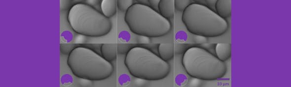
While oblique contrast can significantly improve the visibility of transparent specimens, it also has some limitations. Because image contrast depends on the direction of illumination, the appearance of a sample can change considerably when either the specimen or the illumination angle is rotated. This can sometimes introduce image artefacts or emphasise certain structures while obscuring others.
Like Differential Interference Contrast (DIC), oblique contrast produces a pseudo three-dimensional appearance. However, the light and shadow effects seen in the image do not necessarily represent the true geometry of the specimen and can create the impression of depth where none exists.
Oblique contrast is therefore best suited to qualitative visualisation rather than quantitative assessment of sample morphology. In addition, because only part of the available illumination cone is used, the full numerical aperture of the condenser and objective is not utilised, which can lead to a reduction in image resolution compared with some other contrast techniques.
How Oblique Contrast Works
In conventional brightfield microscopy, light passes through the specimen along the optical axis. Although transparent structures within the sample alter the phase of the transmitted light, these phase differences often produce very little visible contrast, making fine details difficult to distinguish.
Oblique contrast enhances these subtle phase differences by illuminating the specimen from one side rather than directly beneath it. This is achieved using a condenser fitted with a sector stop containing an off-centre slit. The slit restricts the illumination so that light enters the specimen at an oblique angle instead of travelling along the optical axis.
As the angled light passes through the specimen, it is diffracted by structures within the sample. After entering the objective lens, the direct and diffracted light rays recombine at the rear focal plane. Because illumination is coming from a single direction, only part of the diffracted light distribution is collected by the objective. This creates an imbalance between the direct and diffracted light components, converting phase variations within the specimen into differences in image intensity.
The result is an image with enhanced contrast and characteristic light-and-shadow effects that give transparent structures a pseudo three-dimensional appearance. These shadowing effects make features that would otherwise be difficult to detect using brightfield microscopy much easier to visualise.
Key principle: Oblique illumination causes only part of the diffracted light distribution to enter the objective, converting phase differences within transparent specimens into visible image contrast.

Figure 1a shows a typical oblique contrast configuration, where the specimen is illuminated from an off-axis direction. Figure 1b illustrates how only one side of the diffracted light distribution is collected by the objective, generating the contrast-enhancing interference that characterises oblique contrast microscopy.
How to set up Oblique Contrast
Step 1: Install the Oblique Condenser
Oblique contrast can be added to a standard brightfield microscope using an oblique condenser and a suitable visible or infrared light source. Once Koehler illumination has been established, the condenser iris and sector stop can be adjusted to achieve the desired level of contrast and directional illumination.
To make a brightfield microscope capable of oblique contrast, the only additional components required are an oblique condenser and an infrared or visible light source.
Place the oblique condenser in the condenser housing above the light source. The oblique contrast mechanism (sector stop) is located below the condenser lens and aperture diaphragm.

Figure 2: An oblique condenser with the diaphragm control knob and condenser iris lever labelled.
Step 2: Configure Brightfield Illumination
Firstly, pull out the oblique slider and open the oblique iris so that the condenser is adjusted for brightfield illumination.

Figure 3: An oblique condenser with the condenser iris fully open and oblique slider fully out to enable brightfield illumination.
Step 3: Set Up Koehler Illumination
Establish Koehler illumination on the microscope. If using a manual microscope, remove the condenser stop before setting up Koehler illumination and replace it afterwards.
Step 4: Match the Condenser Iris to the Objective
Close down the condenser iris to match the numerical aperture of the objective.

Figure 4a (left) shows the condenser iris fully open. The sector stop can be seen below. Figure 4b (right) shows the condenser iris partially open based on the numerical aperture of the objective.
Step 5: Adjust the Sector Stop
Adjust the direction of the sector stop by turning the diaphragm control knob. Close down or open the stop to adjust the amount of oblique illumination until the desired image is achieved.
The amount of oblique illumination required will depend on the specimen and the amount of detail required. The oblique condenser enables the angle of illumination to be altered through 360° without moving the specimen.

Figure 5: The condenser iris and sector stop have been adjusted, leaving a small slit for light to pass through.
Step 6: Fine-Tune the Image
Continue adjusting the sector stop as required while observing the image. When making adjustments, check that the sector stop is still positioned correctly and that the slider is not too far in or out.
Your microscope is now set up for oblique contrast. Please contact Scientifica if you have any questions or require any further guidance.
Conclusion
Oblique contrast is a simple and versatile technique for improving the visibility of transparent, unstained specimens. Its low cost, ease of use and compatibility with birefringent samples make it a valuable alternative to more complex contrast methods, particularly in neuroscience, electrophysiology and live-cell imaging applications. Although the images produced should be interpreted carefully, oblique contrast remains an effective way of revealing fine structural detail that would otherwise be difficult to observe using brightfield microscopy.
Learn about other contrast techniques
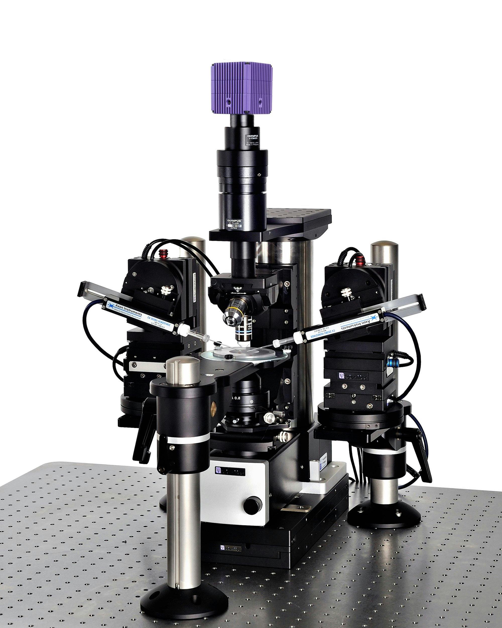
Scientifica SliceScope Pro 1000
An integrated electrophysiology system for patch clamp recording. The versatility of the system means that you can perform slice electrophysiology, fluorescent imaging, and in vivo experiments.
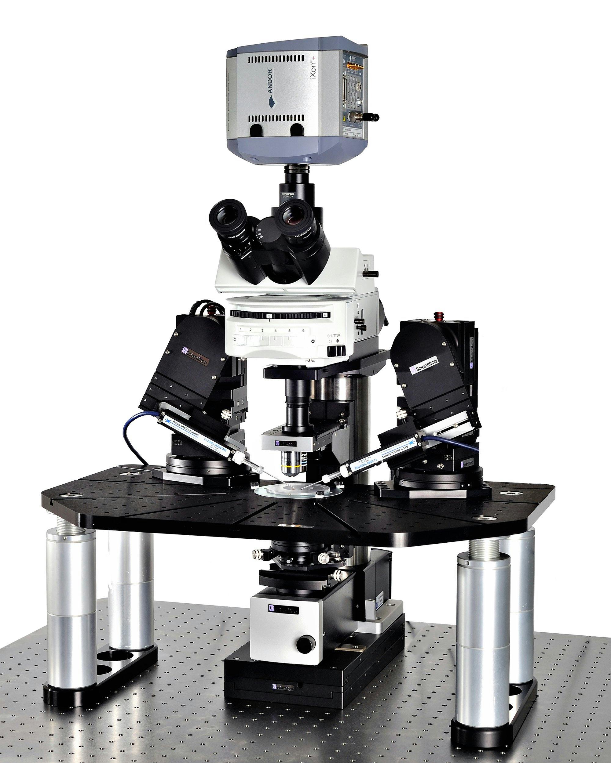
Scientifica SliceScope Pro 2000
The SliceScope Pro 2000 is an integrated electrophysiology system for patch clamp recording incorporating a large mounting stage. The versatility of the system means that you can perform slice electrophysiology, fluorescent imaging, and optogenetics.

Scientifica SliceScope Pro 3000
A static microscope system designed for in vitro electrophysiology experiments and capable of accommodating advanced imaging, such as two-photon and confocal.