

#LabHacks: Checking the alignment of your Galvo mirrors
Following our popular guide that explains how to align your laser for two-photon imaging, here is another helpful guide demonstrating how to check the alignment of your HyperScope Galvo mirrors.
Parking the scan mirrors in the centre of their travel
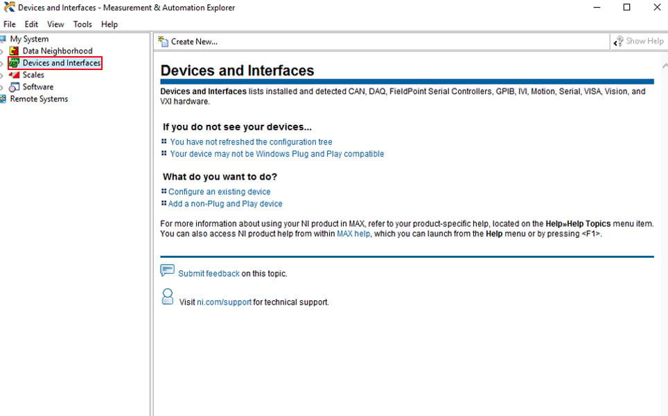
1. Open NI MAX. This is an application provided by National Instruments to directly communicate with their data acquisition devices. This should already be installed on your PC, click here for more information.
2. Click on Devices and Interfaces to expand the list of connected acquisition devices.
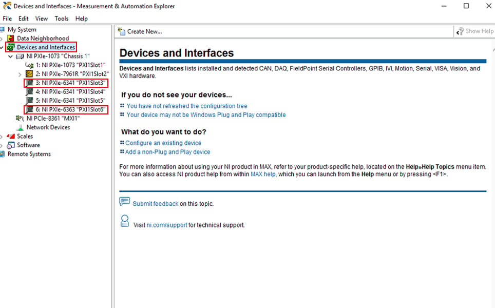
3. From the device list, choose the device that is controlling the Galvos you want to align. If you are unsure which device to choose you can either:
a. Check the software configuration file to see which device is specified to drive your scanning mirrors
b. Follow the command cables from the Galvo drive cards back to the data acquisition breakout box and then back to the DAQ card itself.
In our example, “PXI1Slot3” is controlling one set of scanning mirrors while “PXI1Slot6” is controlling a second pair.
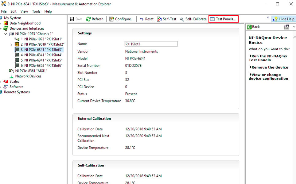
4. Select the card controlling the first set of Galvos that you wish to align. Click on the Test Panels button to bring up the Test Panels window.
5. Click on Analog Output in the Test Panel window.
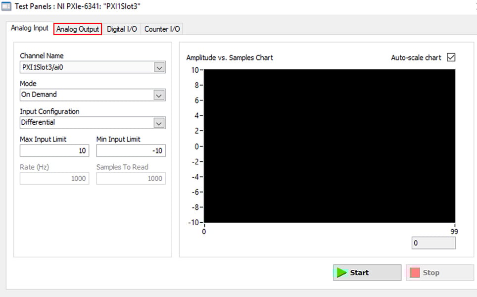
6. Click on the dropdown arrow beneath ‘Channel Name’ and select PXI 1Slot3/ao0. Type ‘0’ into the Output Value (V) and click ‘Update’. This places the X-Galvo mirror in the centre of its travel range.
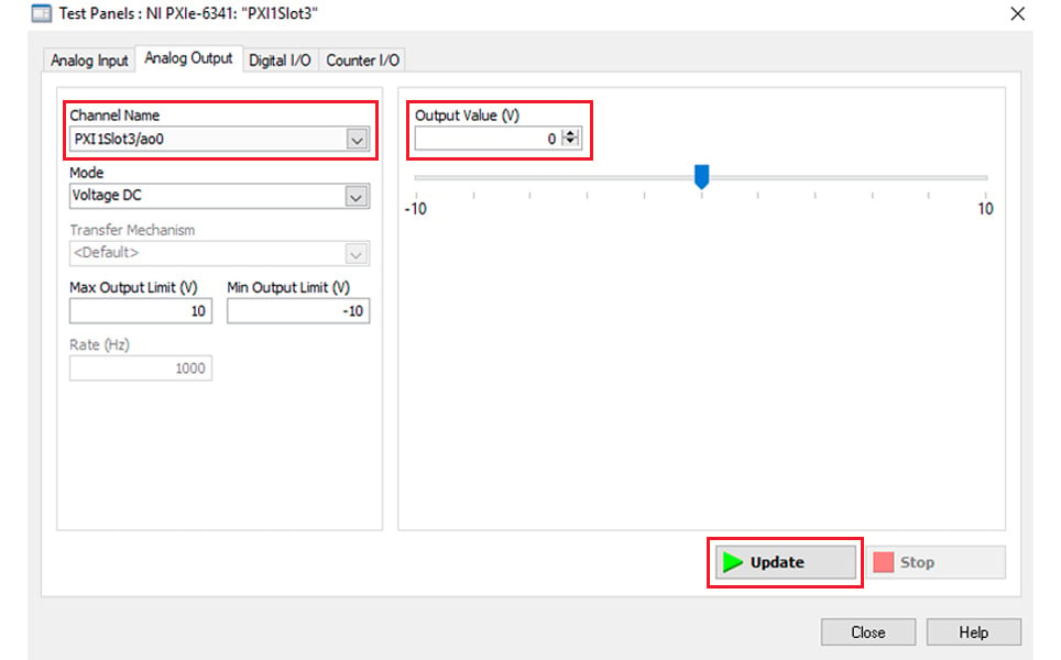
7. Repeat step 6 but select PXI 1Slot3/ao1 from ‘Channel Name’. Again type ‘0’ into the Output Value (V) and click ‘Update’. This places the Y-Galvo mirror in the centre of its travel range.
8. Leave the Test Panels window up while you align the Galvo mirrors.
Aligning the Galvo mirrors
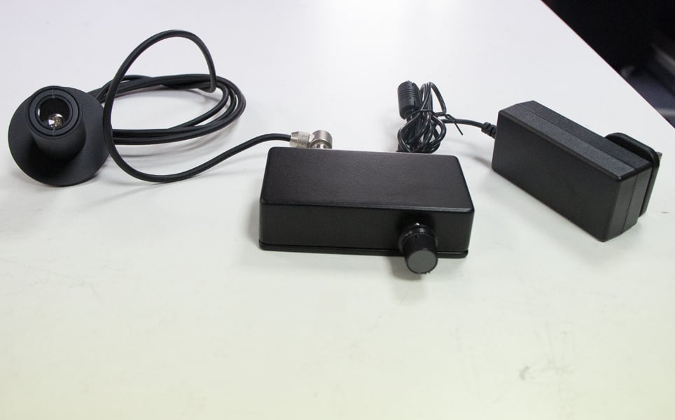
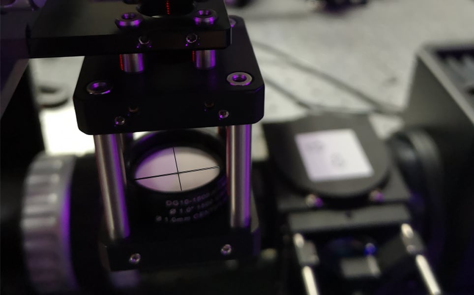
Pictured above is the alignment tool that you will be using to align the Galvo mirrors. If you don’t have a Scientifica LED alignment tool, the same principle can be achieved using a sample with a crosshair along with a bright visible transmitted light source (for example, your phone torch).
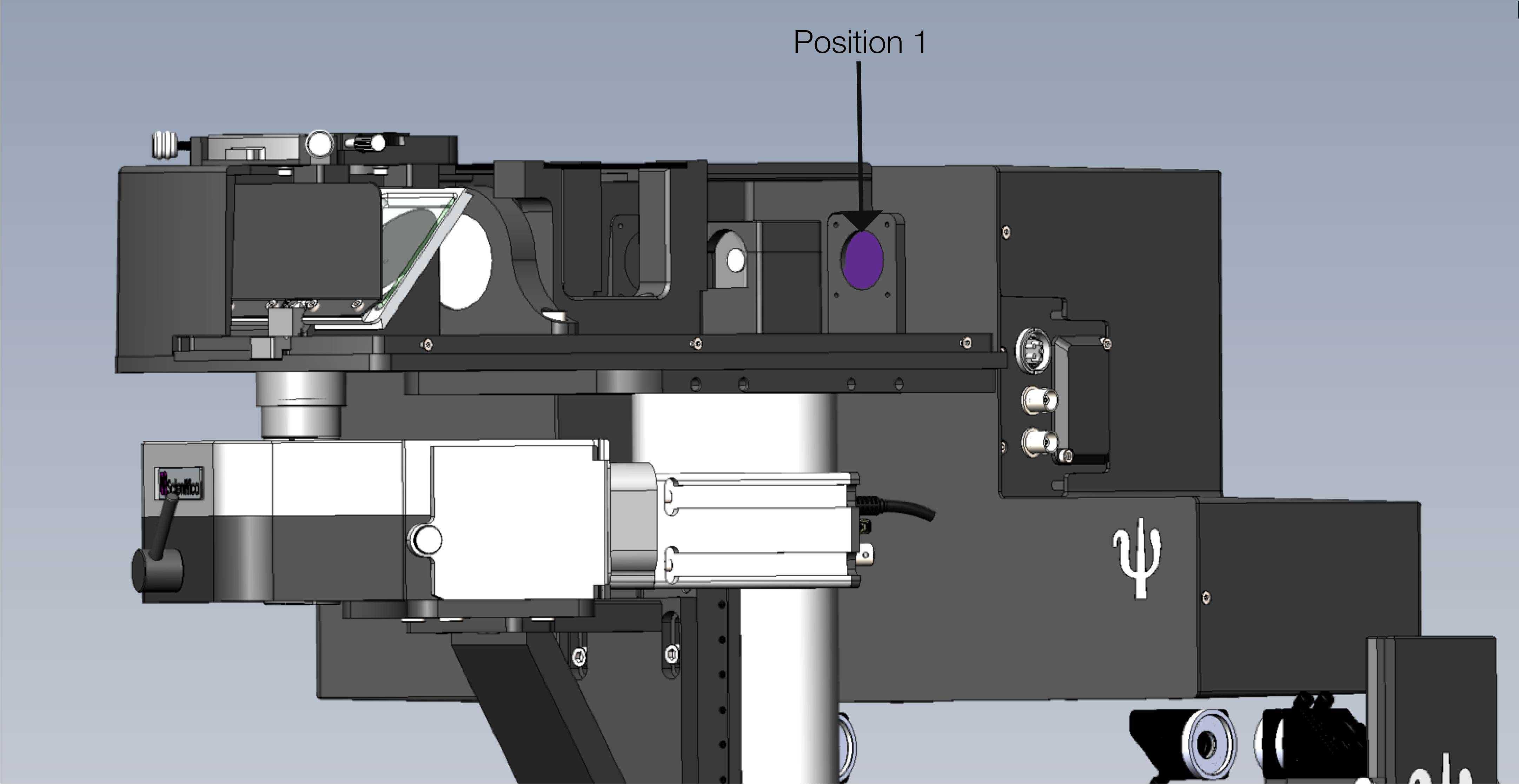
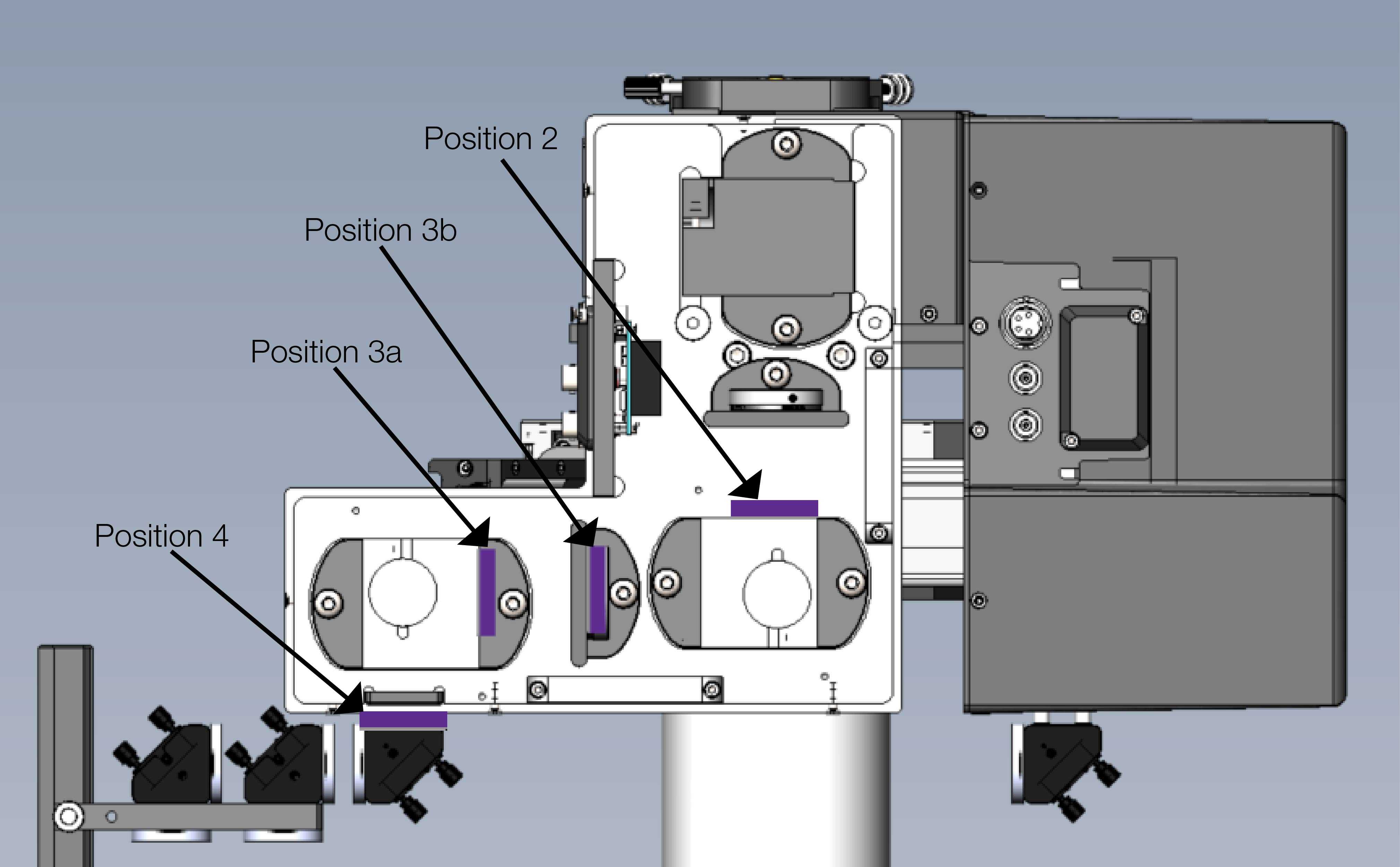
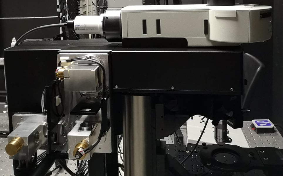
For reference, here are two diagrams of the HyperScope that demonstrate the positions we will be referring to throughout this guide:
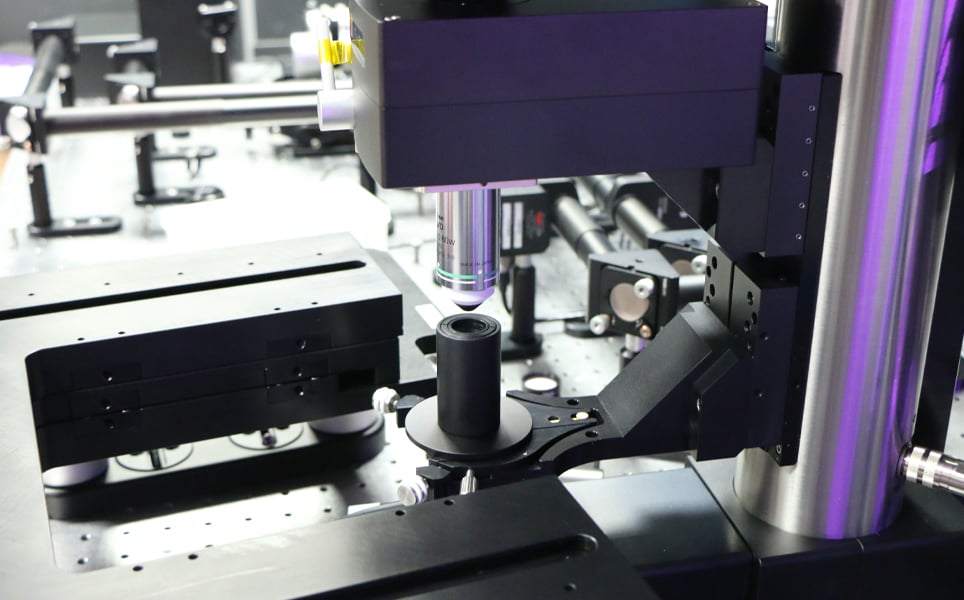
1. Position the alignment tool directly under the objective, using either the condenser arm in the case of a SliceScope frame or by mounting it on a post of a VivoScope frame. Pictured below is the alignment tool in the condenser arm of a SliceScope.
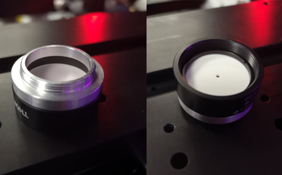
2. Fasten the IR disc into the frosted glass disc to improve the contrast of the LED on the frosted glass disc during alignment. Insert the IR disc backwards, so the white side of it is facing outwards.
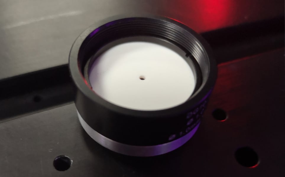
3. Screw the frosted glass disc into the SM1 threaded aperture (position 1 on the diagram) located between the scan lens and the polarising beam combining cube.
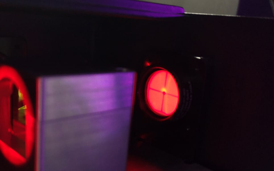
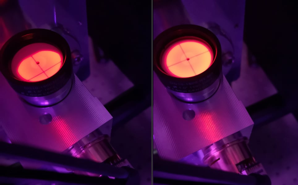
4. Adjust the position of the LED under the objective until the crosshair is centred on the glass disc.
Turn the lights off to see the crosshair more clearly
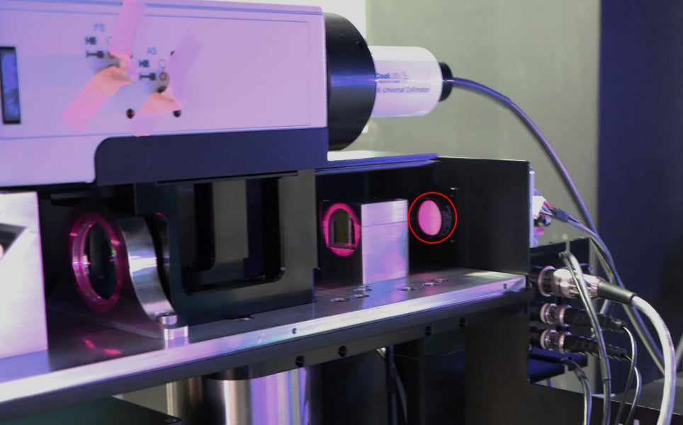
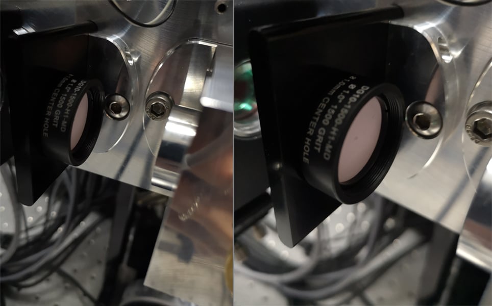
Before alignment:
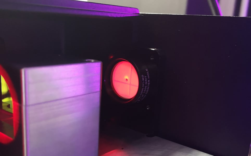
After alignment:
5. Remove the frosted glass disc from the position between the combining cube and scan lens
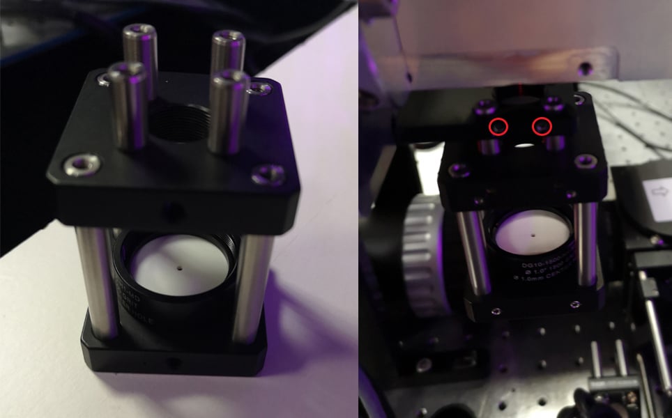
6. Attach the thread adaptor to the alignment target, as shown below
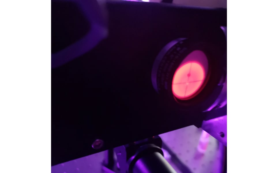
7. Screw the alignment target into the relay lens carrier (position 2) located between the X- and Y-Galvo
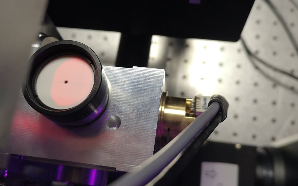
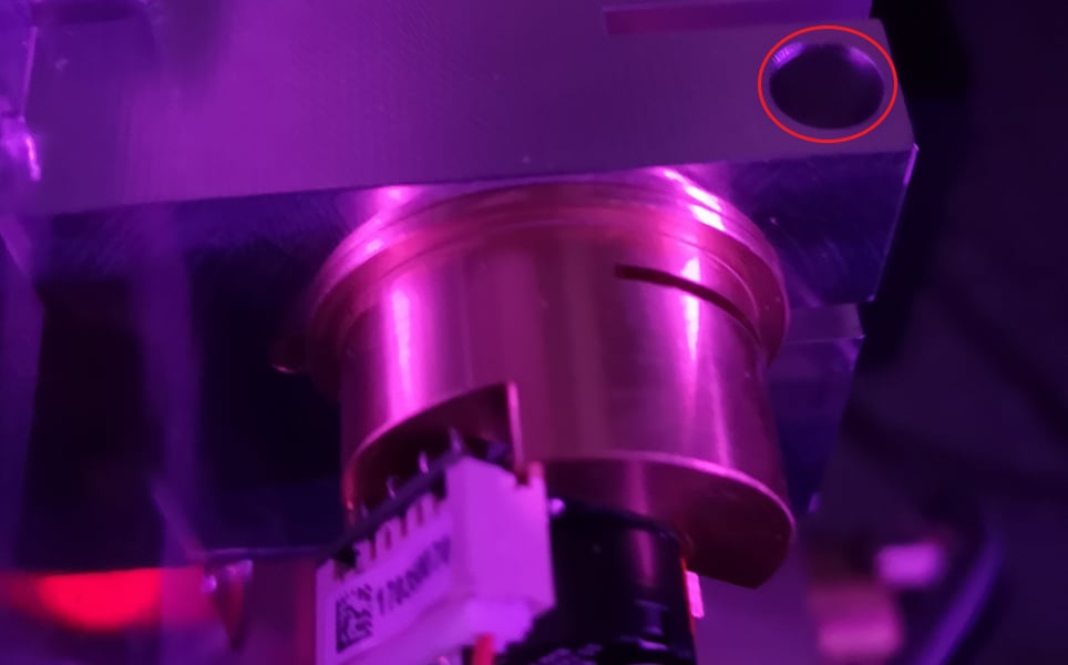
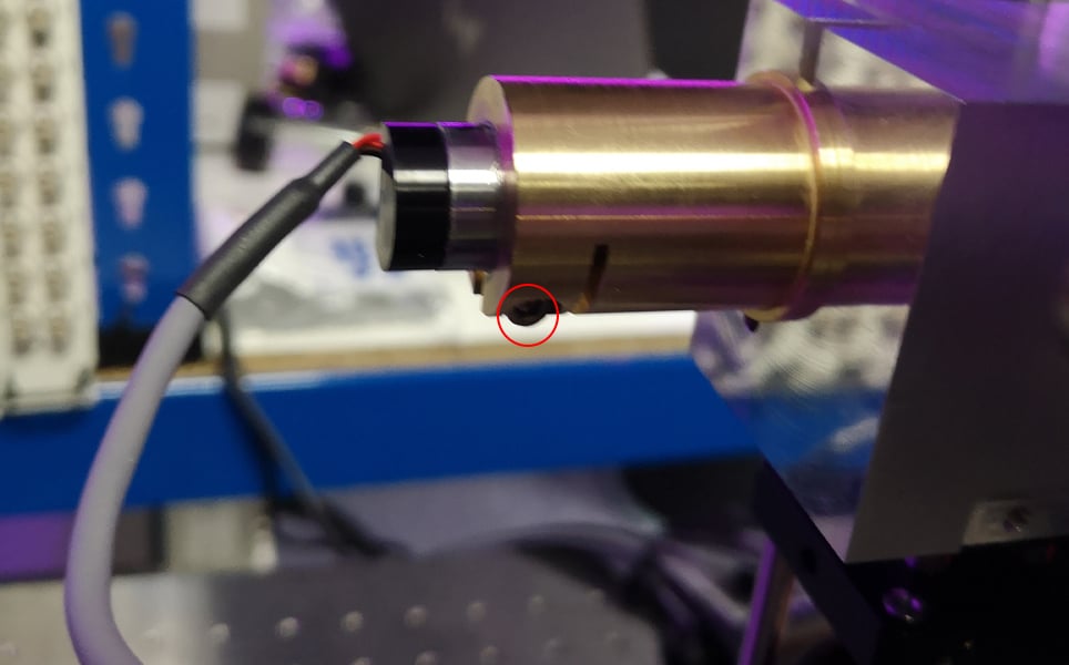
8. Rotate the Y-Galvo in its housing to re-centre the crosshair on the alignment target.
Do this by loosening the 2.5mm screw that clamps the brass holder into the Galvo housing (circled in the figure below). Rotate the brass holder until the cross is aligned, then tighten the screw again to secure it.
Before and after alignment
If the cross moves when the Galvo is locked, unlock it again and realign.
9. Remove the alignment target from between the X and Y-Galvo and attach it to the relay lens carrier positioned between the x-reso and X-Galvo mirrors (position 3a).
10. Rotate the X-Galvo inside its housing to re-centre the crosshair on the alignment target. Do this by loosening the 2.5mm screw that secures the brass holder to the Galvo housing. Rotate the brass holder until the cross is aligned, then tighten the screw again to secure it.
11. Remove the small mirror situated between the periscope and the first scanning mirror, which hangs below the scan path (position 4), with a 1.5mm Allen key. Replace this with the holder containing the alignment target, pictured below. The front two screws are circled, the back two screws cannot be seen.
12. Remove the resonant sound cover, using a 2.5mm Allen key.
First, unscrew the two screws holding the two parts of the sound cover together. In the image below, you can see one is being unscrewed and the other is circled.
Secondly, unscrew the two screws holding the sound cover down. In the image below, one of these is being unscrewed and the other is circled.
The image below shows the HyperScope with the sound cover removed, exposing the light path.
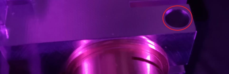
13. Loosen the screw circled and rotate the resonant mirror to align it to the centre of the alignment target (the cross is hard to see in the photo below, so we have added the cross to help make it clearer).
14. Tighten the locking screw once centred.
15. If you are only using one light path, put the resonant sound cover and small mirror back into position, remove the alignment tool and continue to step 19. If you have a second light path, continue to step 14.
16. After completing the alignment for the imaging path, return to step 3 and select the device controlling your second set of scanning mirrors for the photo stimulation path. Repeat steps 4 – 8, then follow the steps 15 – 19 below to align the mirrors for the photostimulation path.
17. Attach the alignment disc to the threaded aperture situated between the X-Galvo and the fixed (non-scanning) mirror (position 3b) which is Inserted into the block where the resonant scanner is typically installed.
18. Rotate the X-Galvo to align the crosshair to the alignment target,
19. Follow steps 10-12, however in step 12, you will be rotating a fixed mirror instead of the resonant scanning mirror. To do this, loosen the clamping screw in the same position as what was loosened for the Galvo alignment, and centre the crosshair on the alignment target.
20. Remove the alignment target and re-install the small mirror at the scan path input.
21. Double check that all apertures that were used for alignment are now clear of equipment. Ensure all parts that were removed during the alignment process (for example, input mirrors, light path covers, sound enclosures etc.) are replaced before you attempt to image.
22. You are now ready to image!
If you would like any further advice, please contact our team of experts at [email protected].
Take a look at other #LabHacks articles
- #LabHacks: What you need to know about immunolabeling procedures
- #LabHacks: How to align your laser for two-photon imaging
- #LabHacks: Tips for cleaning the optics of your microscope
- #LabHacks: To compensate or not to compensate, that is the question
- #LabHacks: How to reduce the noise around your electrophysiology rig
- #LabHacks: Choosing the best opsin for your optogenetics experiments
- #LabHacks: 14 sharp tips for patch clamping
- #LabHacks: Tips for performing adult animal brain slicing for patch clampers
Sign up to receive our latest news
Find out about Scientifica's latest product releases, company news, and developments through a range of news articles, customer interviews and product demonstration videos.
)