

#LabHacks: Aligning your Pockels cell for two-photon imaging
Following the popularity of our guides demonstrating how to align your laser for two-photon imaging and how to check the alignment of your Galvo mirrors, we have created this guide to help you align your Pockels cell.
Safety advice
Anybody working with lasers should be fully trained and follow the applicable institutional and national laser safety guidelines and legislation. These safety tips are for guidance only and can no way replace laser safety training.
- Do not enter laser rooms unless trained or accompanied by someone who is trained and authorised
- Do not look into the laser beam
- Wear suitable laser safety eye-wear
- Keep room lights on brightly if possible
- Locate and terminate all stray laser beams at an absorbing or diffusely reflecting surface
- Avoid stray laser beam reflections as they could be hazardous to the eyes and skin
- Remove all personal jewellery, including watches
- Clamp all optical components
- Be cautious using IR Detector Cards with glossy surfaces
- Do not use reflective tools
- Keep beams horizontal, if this isn’t possible, be very careful with non-horizontal beams (e.g. flipping mirrors and periscopes)
- Ensure beams are well above or below eye level
- If you need to bend down, always look away from the table
- Do not bend below beam height
- Be extremely cautious when leaning down to beam-level
- Think twice before leaning to table level to get a better look at your experiment
- Do not forget non-optical hazards (e.g. tripping, fire risk)
- Encase the beam as much as possible using beam tubing
- Shutter the beam when putting optical elements, such as mirrors, in place
- Use a beam block behind each optical component to ensure there are no stray laser beams while setting up the next element
The equipment
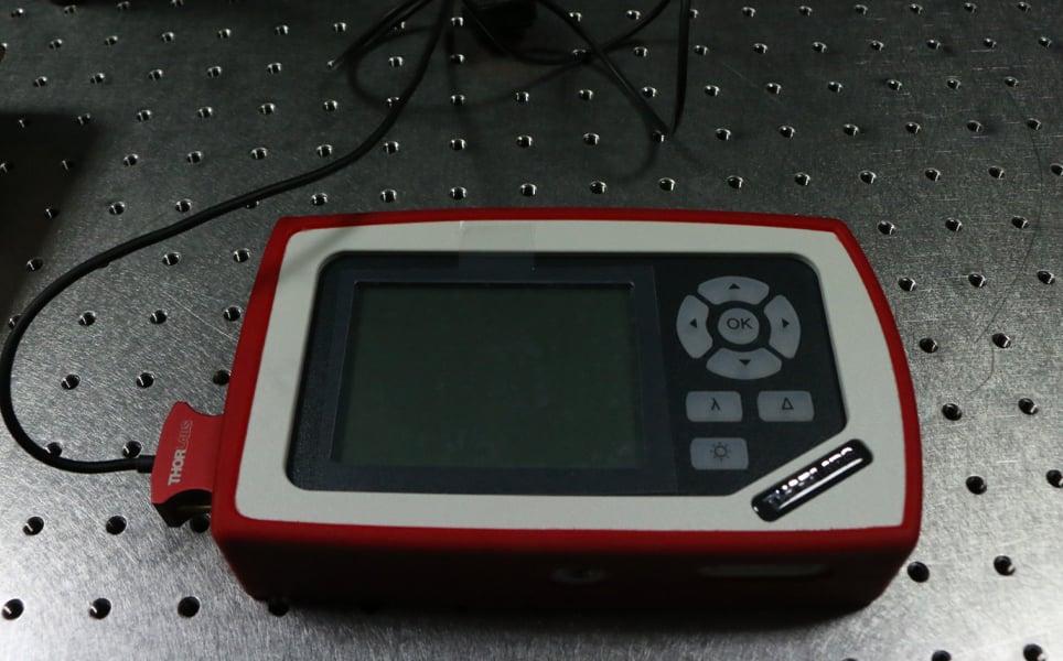
Power meter
Used to measure the power of the laser beam.
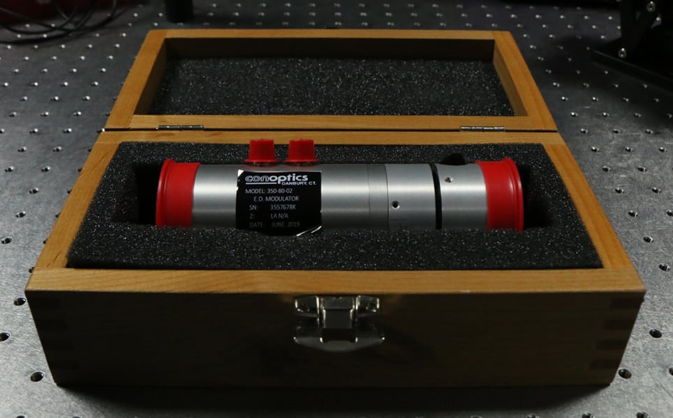
Pockels cell
An electro-optical modulator that attenuates and controls the beam when speed is essential, for example in photostimulation experiments. This is faster, more precise, and more reliable than using the half-wave plate/polarising beam splitter units or Neutral Density filter wheels.
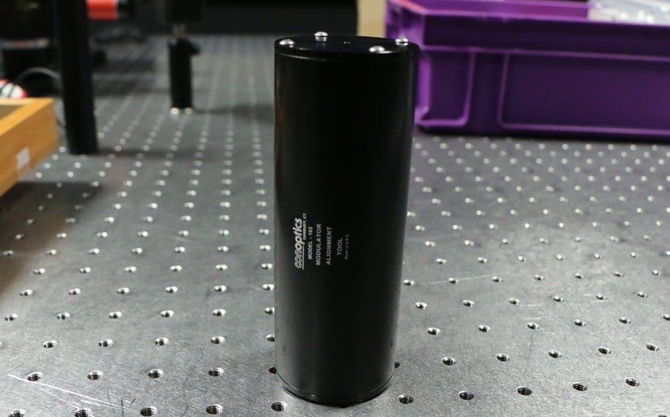
Dummy Pockels cell
This is an alignment tool used to ensure correct positioning before being replaced with the functioning Pockels cell.
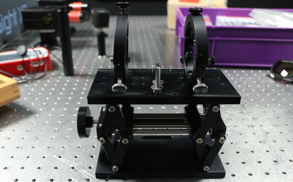
Pockels cell stand
Holds the Pockels cell in position.
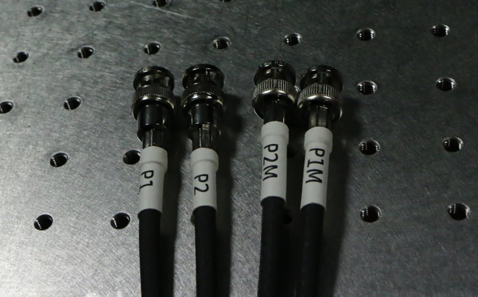
Cables
These connect the Pockels cell to the controller.
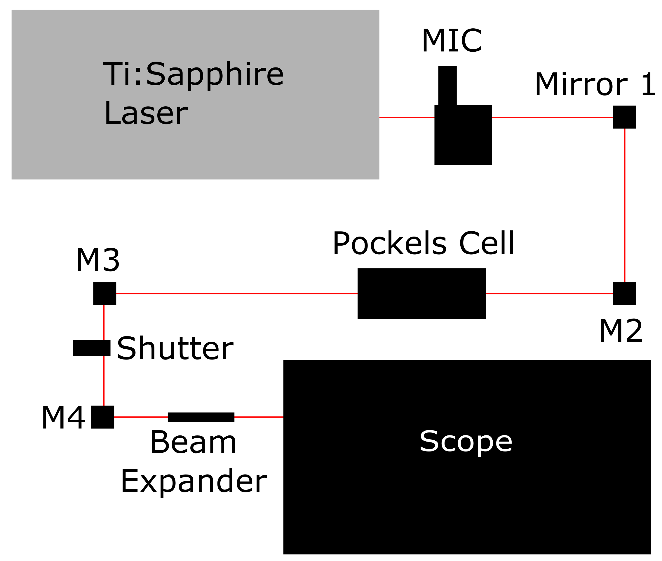
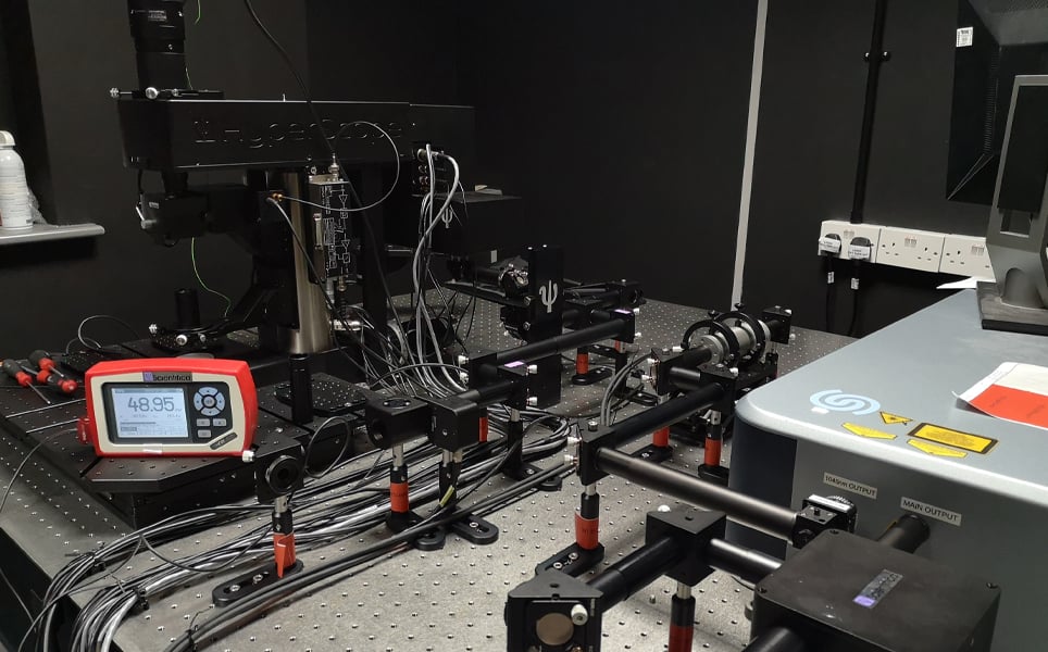
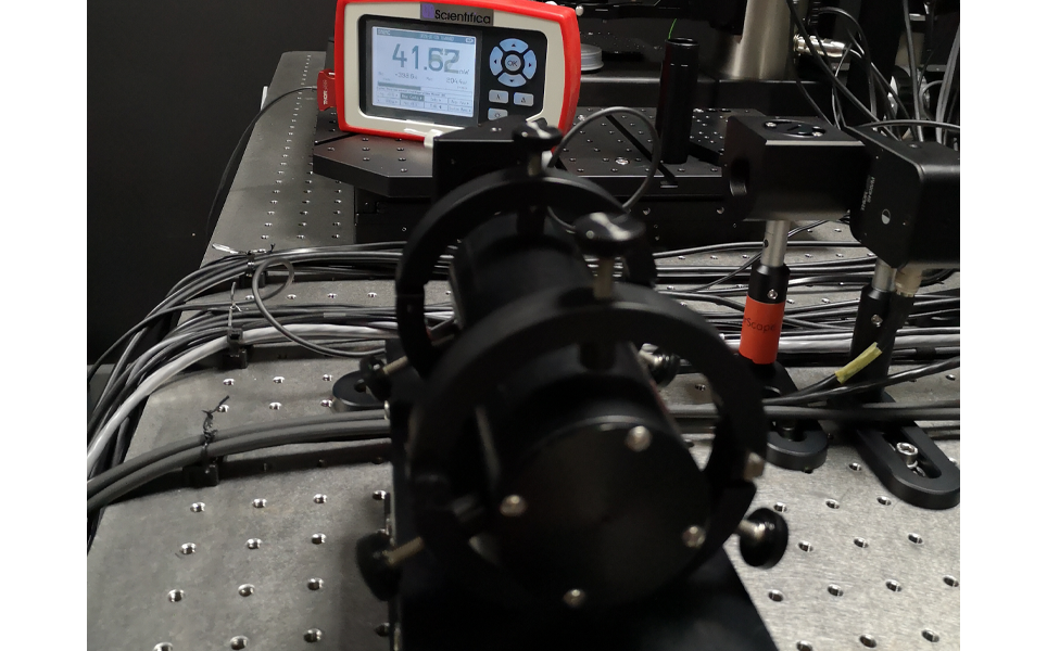
Example multiphoton table layout
Aligning the Pockels cell
1. Decide on the location of the Pockels cell. It is normally placed between two steering mirrors, with a Manual Intensity Controller (MIC) (if using), and at least two steering mirrors being in between the Pockels cell and the laser. Learn more about the role of the MIC and steering mirrors here.
2. Put the laser into alignment mode. The alignment mode should never be used for more than 20 minutes, followed by at least a 10-minute break to allow the laser to cool off
Please note, the alignment mode of the laser does not protect eyes; it is designed to protect equipment
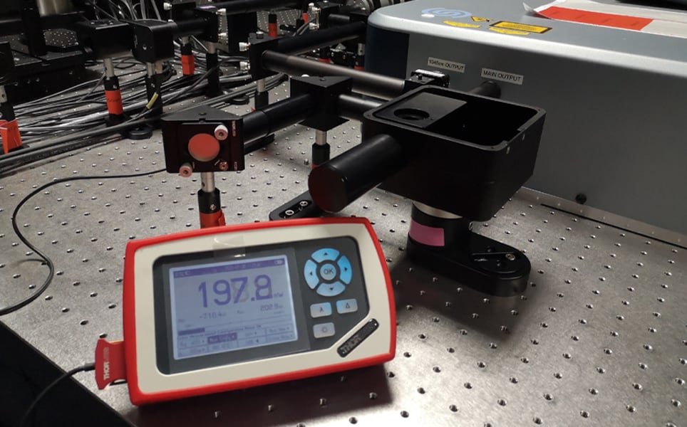
3. Attach the power meter to a mirror before the Pockels cell and use this to check the power of the laser. We attached the power meter to M2.
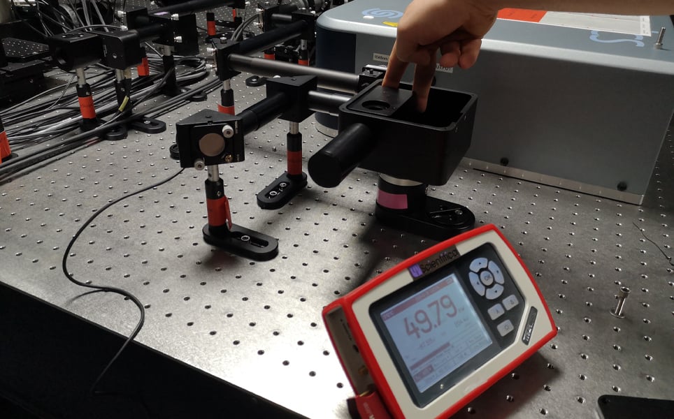
4. Attenuate the laser using the MIC - open the MIC lid and rotate the half waveplate to attenuate the beam. If using an AOM laser, attenuate the laser using the software provided.
We attenuated the beam from 200mW – 50mW.
5. Attach the power meter to a mirror that is positioned after the Pockels cell (which is not yet in position). We attached it to M3.
6. Align the laser to the centre of the irises of the mirrors that will be either side of the Pockels cell – in this case it is M2 and M3. For more information about how to do this, take a look at our guide for aligning your laser for two-photon imaging.
7. Make a note of the value shown on the power meter after the laser is aligned to the centre of the irises.
8. Shutter the laser.
To prevent injury, it is important to remember to shutter the laser before positioning any piece of equipment.
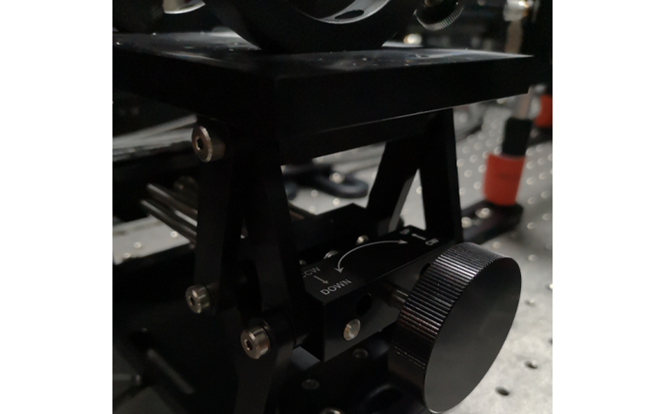
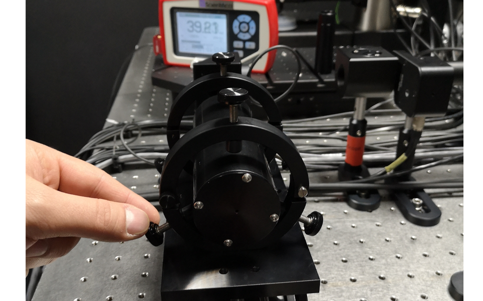
9. Set the Pockels cell stand to its maximum height by adjusting the knob.
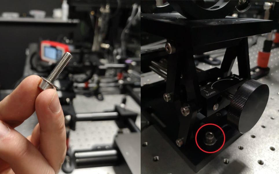
10. Place the Pockels cell stand into position. Ensure it is in the centre of the mirrors that are either side of it. Screw it down using the screw and washer, ensuring it isn’t too tight as you may need to make adjustments.
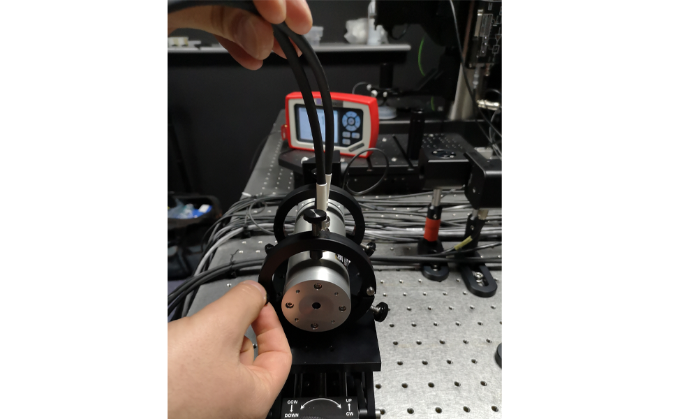
12. Place the dummy Pockels cell alignment tool into the Pockels cell stand and close the holder.
13. Unshutter the laser.
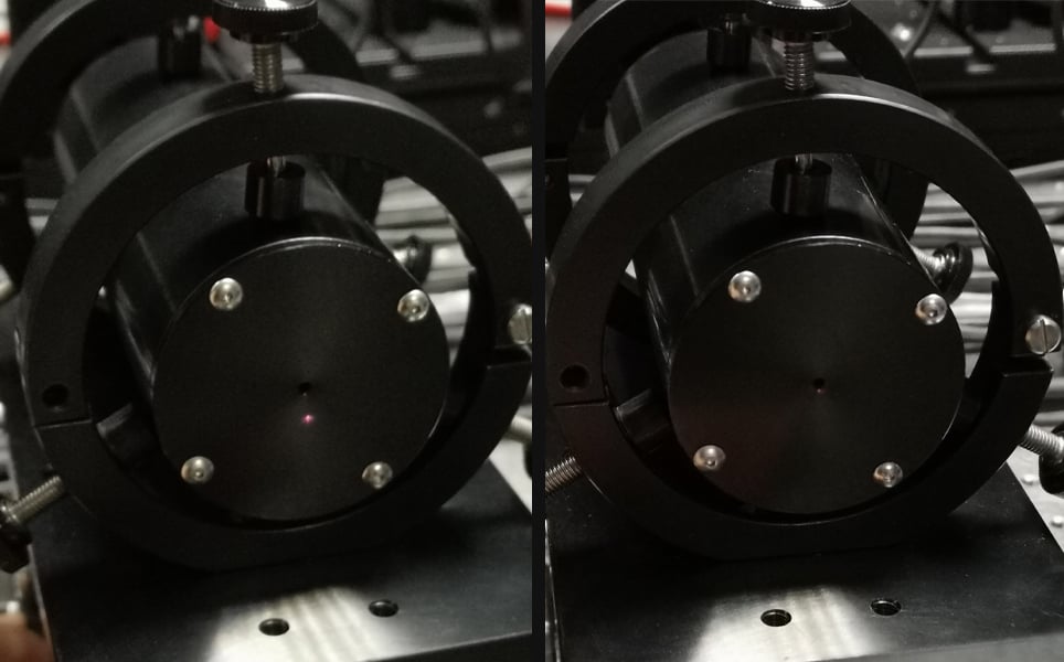
14. Lower the stand until the hole in the centre of the alignment tool is roughly the same height as the laser beam.
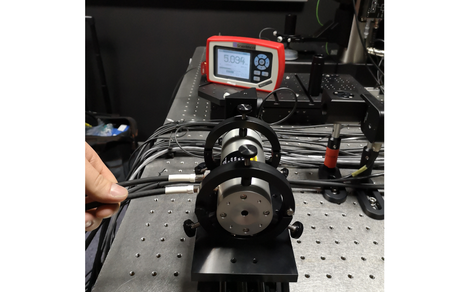
15. Adjust the position of the alignment tool so the laser beam is aligned to the centre of it, by moving it vertically or horizontally. You will see the power reading on the power meter change as this is happening. Adjust the position of the alignment tool until the power meter value is within approximately 90% of the value you noted in step 7.
16. Shutter the laser. Tighten the screws of the Pockels cell holder so the alignment tool is secured. Be careful not to cause too much movement of the holder as this will alter the alignment.
17. Unshutter the laser.
18. Ensure the power of the laser beam going through the alignment tool is the same as before the screws were tightened. Adjust the lower knobs of each ring on the stand holding the alignment tool to get the power to within 90% of the noted power. Leave the upper knob loose enough so you can rotate the Pockels cell in a later step.
19. Shutter the laser.
20. Ensure that the controller of the Pockels cell is switched off.

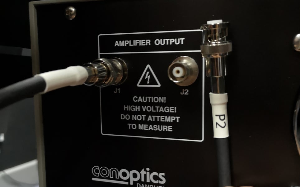
21. Remove the plugs from the Pockels cell and plug in the cables. The end labelled ‘P1M’ is plugged into ‘J1M’ on the Pockels cell and the end of the cable labelled ‘P2M’ goes into ‘J2M’ on the Pockels cell.
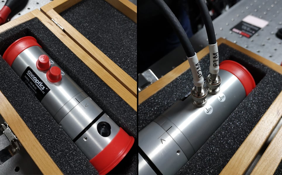
22. The end of the cable labelled ‘P1’ goes into ‘J1’ of the controller and ‘P2’ is plugged into ‘J2’ on the controller.
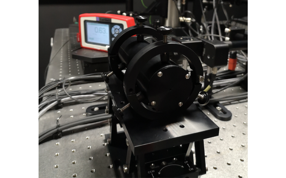
23. Remove the alignment tool from the holder and replace it with the Pockels cell. Be careful not to change the position of the adjustment knobs. Ensure the end of the Pockels cell with the beam dump is located at the furthest point from the laser.
24. Lock the Pockels cell into position by tightening the screws on the side of the holder.
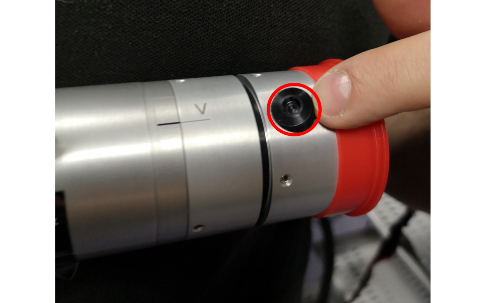
25. Rotate the Pockels cell, taking care to ensure the cables are not forced, to change the polarisation of the laser. By looking at the power meter, rotate the laser until you get the maximum laser power passing through the Pockels cell.
26. Adjust the screw on top of the holder to temporarily secure the Pockels cell in place.
27. Adjust the MIC to provide the maximum laser power you need for your sample.
28. Release the top knob and rotate the Pockels cell, taking care to ensure the cables are not forced, to change the polarisation of the laser and minimise the power. The minimum laser power needs to be passing through the Pockels cell.
29. Adjust the knobs on top of the holder to fully secure the Pockels cell.
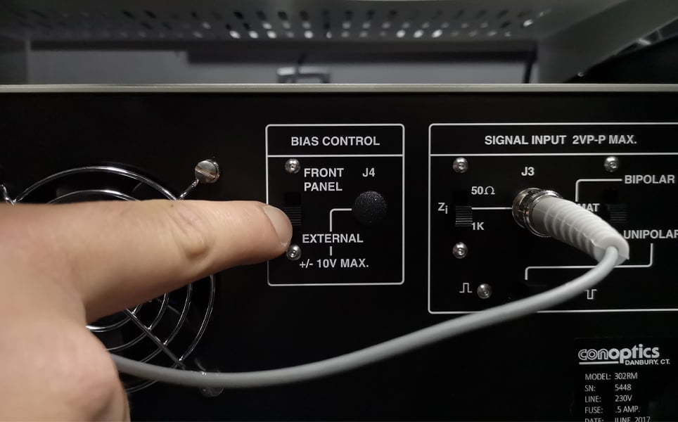
30. Ensure the settings on the Pockels cell control panel are as follows:
- Bias control – front panel
- Signal input – impedance at 1Khm
- Square wave – positive
- Format – unipolar
31. Turn the laser on and turn the driver on.
32. Read the power meter.
33. Adjust the bias on the front of the controller until the smallest power possible is read. The controller bias should be close to 0.
34. In the multiphoton software, change the percentage of the power on the software. As you change the percentage, there should be a linear change in the power meter.
Your Pockels cell is now aligned. If you would like any further advice, please contact our team of experts at [email protected].
Take a look at our other #LabHacks articles:
- #LabHacks: Checking the alignment of your Galvo mirrors
- #LabHacks: How to align your laser for two-photon imaging
- #LabHacks: Tips for cleaning the optics of your microscope
- #LabHacks: Tips for improving your electrophysiology experiments
- #LabHacks: To compensate or not to compensate, that is the question
- #LabHacks: How to reduce the noise around your electrophysiology rig
- #LabHacks: Choosing the best opsin for your optogenetics experiments
- #LabHacks: 14 sharp tips for patch clamping
- #LabHacks: Tips for performing adult animal brain slicing for patch clampers
Sign up to receive our latest news
Find out about Scientifica's latest product releases, company news, and developments through a range of news articles, customer interviews and product demonstration videos.
)