Patch clamp techniques for investigating neuronal electrophysiology

by Joern Steinert, University of Leicester
Introduction
Patch clamp electrophysiology is used to study the electrical properties of excitable cells and ion channels. In patch clamp experiments, suction is used to attach a micropipette filled with electrolyte solution to the cell membrane. This forms a seal, isolating a patch of the membrane to enable the flow of currents across this section of the membrane to be measured. Researchers are able to ‘clamp’ or control the voltage across the membrane and measure the current passing through it (voltage clamp), or ‘clamp’ the current and measure the variation of the voltage across the membrane (current clamp).
Here, we describe the different types of patch clamp techniques and when you would use each.
Recording Configurations
There are three core electrophysiological techniques used to study how cells — particularly neurons and excitable cells — generate and respond to electrical signals
Voltage clamp
Much of our knowledge about the functioning of ion channels has come from experiments using voltage clamp. Voltage clamp recordings allow the ion flow across a cell membrane to be characterised by measuring the electrical current, whilst controlling the voltage using a feedback amplifier. The method was first developed by Hodgkin et al. (1952)1 and used in the squid giant axon in the laboratories of the Marine Biology Association in Plymouth, UK, then further refined by Cole & Moore (1960)2. Since then, many variants of the technique have evolved, with voltage clamp analysis being used in many cell types.
Voltage clamp experiments can be subdivided into whole-cell patch clamping or sharp electrode recordings. Sharp electrode recordings can be carried out with a single sharp electrode or in a two-electrode configuration.
Due to the nature of single electrode voltage clamp, the limitation is given by the size of the series resistance, composed of the membrane resistance and pipette access resistance, to allow for reliable control of the membrane voltage. The higher the series resistance and the flowing current, the higher the voltage error. This error can be minimised by using larger electrodes or recording smaller currents.
However, certain cellular systems, such as the Drosophila neuromuscular junction (NMJ) or Xenopus oocytes can produce currents well above 100 nA. This would generate an enormous voltage error which is impossible to accurately voltage clamp. The best solution in this case is to use two electrodes - one for voltage sensing and one for current injecting. Both are sharp electrodes and filled with 3 M potassium chloride solutions, thereby providing a relatively low resistance (10-30 MΩ) and high conductance. Using this configuration enables large currents to be recorded to reliably characterise whole cell currents.
Current clamp
The physiology of a cell, and specifically a neuron, depends largely on the differential potential of its membrane. This method assesses changes in membrane potential, which occur as a consequence of changes in ion channel activities. For instance, during an action potential of a firing neuron, the membrane depolarises due to sodium influx caused by the opening of voltage-gated sodium channels, followed by hyperpolarisation due to the opening of voltage-gated potassium channels. The sum of all ion channel activities will shape the nature of an action potential and any membrane depolarisation.
For this technique it is again important to consider the series resistance. The recorded voltage is the sum of the membrane voltage and the voltage drop across the access resistance, both of which have to be compensated for. See below for more information about this.
Single channel recordings
It is possible to isolate small areas of membrane over the surface of the tip of the recording electrode. These areas contain, in the best-case scenario, a few single ion channel proteins, allowing the characterisation of single channel units conducting currents in the range of a few pA. This approach can be performed in cell-attached, outside-out or in inside-out mode.
These configurations require an extremely low electrical noise to resolve small single channel currents.
Patch Clamp Techniques
Below are outlined the key patch clamp techniques.

Illustration demonstrating the various patch clamp configurations.
Cell-attached
Cell-attached patch clamp recordings enable the activity of neurons to be recorded without rupturing the membrane. The pipette is sealed to the cell membrane (with a resistance of 1 GΩ or more) and the current passing through ion channels in that area of the membrane is measured. The cell membrane remains intact, with the inner structure of the cell and membrane undisturbed.
Cell-attached patch clamp recordings are widely used to study single channel currents or the summed current of several channels in a patch of membrane, as well as to measure spontaneous cell firing activity, without changing the cytosolic content of the cell.
Inside out
While in the cell-attached patch configuration, the pipette is retracted, separating the patch from the rest of the cell membrane. This exposes the cytosolic surface of the membrane to the bath solution, allowing access to the intracellular side of the channels. This is an ideal technique to study channels that are activated by intracellular ligands, while the experimenter controls the contents of exposing solution.
Whole-cell
While in cell-attached patch configuration, the experimenter applies a short, strong negative pressure in the pipette, sometimes together with a short pulse of high voltage. This will cause the patch of membrane under the pipette to rupture, so the solution within the pipette is in direct contact with the cell’s cytosol.
This technique is the most widely used method for recording the whole cell’s currents. It enables either whole cell currents flowing through the membrane or the membrane potential to be recorded. For example, voltage-gated ion channels, such as voltage-gated potassium or sodium channels can be assessed. In conjunction with pharmacology, this provides an essential method to characterise and describe the behaviour of various ion channels under controlled conditions.
A problem with whole cell recordings can be caused by cell dialysis. This is where intracellular messengers, such as ATP, decrease in concentration because some it flows into the pipette.
Outside-Out
Here, the whole-cell method is applied and then the pipette is retracted after the rupture of the membrane. This causes part of the membrane to detach from the cell and reform into a small, vesicular structure, with the outside of the membrane remaining exposed to the bath solution. This allows the researcher to investigate the properties of single ion channels when they are isolated from the cell. It is easier for the researcher to change the external solution that the patch is exposed to, allowing a dose-response curve to be obtained.
However, it is a more complicated method than those previously described, with more steps that could fail.
Perforated patch
The perforated patch method can be used to prevent cell dialysis. Rather than rupturing the membrane when in the whole-cell configuration, pore-forming agents are used to permeabilise the patch of the membrane that is in contact with the micropipette. These agents are added to the pipette solution, and the procedure for the whole-cell configuration is carried out, without rupturing the membrane.
The pores formed allow small monovalent ions to permeate the membrane while excluding larger ions, such as Ca2+. This minimises disruption to the cell, allowing recordings to be taken over a longer period of time. However, due to the increased access resistance, there may be a lower signal-to-noise ratio.
Perforated-cell patch clamp is used to measure the sum of activity of ion channels in the membrane of a single cell. It is ideal for recording whole cell currents without disrupting second messenger signalling cascades.
Sharp electrode recordings
In this technique, the tip of the micropipette is much smaller (~100 nm). This allows very little ion exchange between the intracellular solution and the electrolyte in the pipette. The resistance of the micropipette electrode is tens or hundreds of MΩ. The technique allows the direct recording of electrical activity generated by the neuron, including the membrane potential, resistance, time constant, synaptic potentials, synaptic currents and action potentials.
Although this technique is relatively difficult to perform (compared to patch clamp), sharp electrode recordings allow experiments to be conducted for longer periods, without the common problems of dialysis and run-down that affect neurons recorded using patch clamp.
Series resistance
In every experiment, there is a resistance across the membrane and the recording electrode (or access resistance) that is in series (Rs). When a current I flows across the membrane this resistance leads to an inconsistency, or error, between the measured membrane potential Vm and the true potential difference across the membrane. The measured membrane potential is the command potential controlled by the amplifier.
High series resistance can often be a problem in whole-cell patch clamp experiments. The access resistance (Ra) of the pipette contributes strongly to the overall series resistance and is usually in the order of a few MΩ resulting in an additional voltage error (ΔV). In particular, permeabilised patch clamp whole-cell recordings using nystatin or amphotericin B usually have 2- to 3-fold higher series resistance compared to normal whole-cell recordings. This automatically comes with correspondingly greater problems to achieve the command voltage.
The size of the voltage error follows Ohm’s law. That is I×Rs, which causes a bigger problem when large currents are flowing, or series resistances are too high. The usual approach is to measure Rs and to decide whether the error ΔV is high and can disturb any measurements. If so, compensation for Rs may be required by adding a voltage signal proportional to the membrane current and scaled appropriately to the command voltage of the clamping amplifier. Usually the level of compensation is set at around 80-90% of the measured Rs using circuitry provided in most commercial patch clamp amplifiers. Series resistance is usually measured under voltage clamp by applying a step change in voltage and measuring the resulting current.
Conclusion
Cell electrophysiology provides the experimenter with an instantaneous result. The various techniques can be applied depending on the question asked, each having their benefits and drawbacks. An extremely helpful and highly recommended training workshop which covers many aspects of electrophysiology, as well as live imaging, is provided annually at the Cell Physiology Workshop in Liverpool (formerly Plymouth). Scientifica's electrophysiology equipment is used during this course.
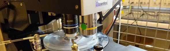
Scientifica's Electrophysiology Rigs
We provide motorised systems and configurations for both upright and inverted microscopes, as well as flexible setups designed to work around your existing equipment — supporting a wide range of neuroscience, cardiac and other research applications

References
- Hodgkin, A. L., Huxley, A. F. & Katz, B. Measurement of current-voltage relations in the membrane of the giant axon of Loligo. J Physiol 116, 424-448, doi:10.1113/jphysiol.1952.sp004716 (1952).
- Cole, K. S. & Moore, J. W. Ionic current measurements in the squid giant axon membrane. J Gen Physiol 44, 123-167, doi:10.1085/jgp.44.1.123 (1960).
This article has been updated from the original layout and design first published on 10th March 2020.