A Deeper Look: Dispersion Compensation
Second-order dispersion (i.e. group velocity dispersion – see definitions below) and its effect on multiphoton imaging was introduced in the first part of this series. Here, we will consider a few additional effects as well as looking at the simplest form of dispersion compensation: the prism pre-chirper.
Second order dispersion vocabulary
Different terms are used when talking about second-order dispersion. These describe related but different aspects of second order dispersion and are not all interchangeable.
- GVD (group velocity dispersion) is a material specific constant, describing how a given material affects light of different wavelengths. Being a constant, it cannot be changed and is specified in fs2 per unit length (commonly fs2/mm).
- GDD (group delay dispersion) is the integral of GVD over the length of an optical element. Also, in an optical system with multiple dispersive elements, the system GDD is the sum of the GDD for all those elements. Because of this, it is possible to change the GDD of an optical system by adding compensatory elements. GDD is specified as fs2.
- The term “chirp” generally refers to the GDD of a system. It describes the fact that the different frequencies in a pulse are separated in time, with the lower frequencies running ahead of the shorter ones. In sound waves, this spread of frequencies results in a chirping sound, leading to the use of the term in optics.
Introduction
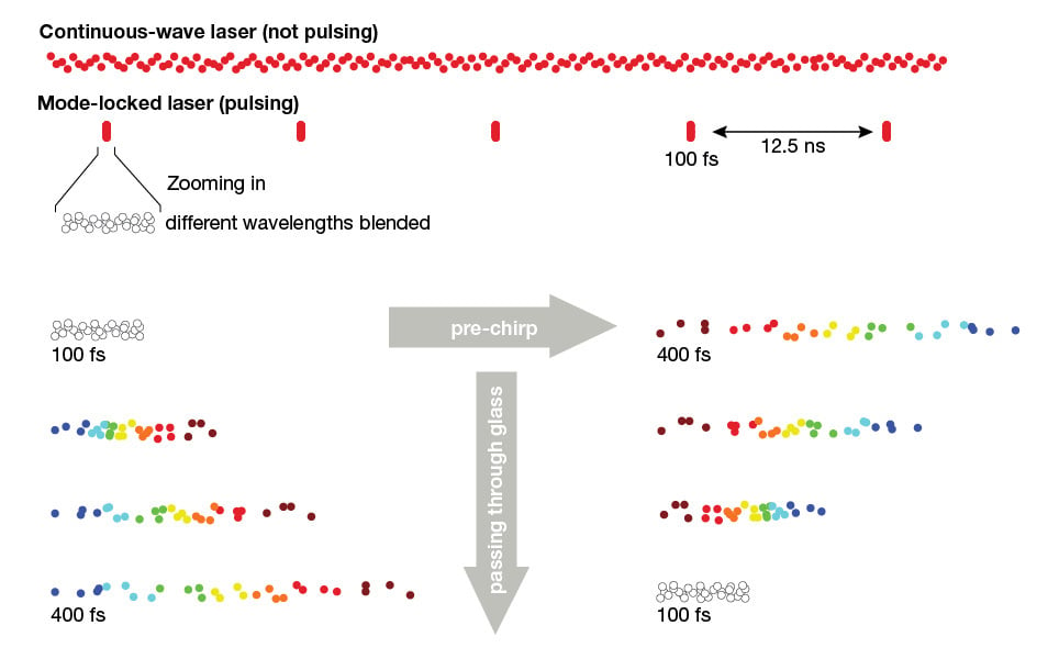
For multiphoton excitation, be it two-photon or three-photon, peak power is the dominant factor determining excitation efficacy of a single laser pulse. The peak power of a laser pulse is the pulse energy divided by the pulse duration (where the pulse energy is the average laser power divided by the laser repetition rate). So, for a given pulse energy, the shorter the pulse duration, the higher the peak power and the brighter fluorescence excited by the pulse. At the same time, only energy in the actual core pulse will contribute to the peak power. To take an extreme example: in a poorly pulsing Ti:Sa laser that has continuous wave break through (i.e. the laser pulses are adding on to a steady laser emission), the average power in the breakthrough does not contribute exciting fluorescence, only adding heat to the sample.
In two-photon microscopy, second order dispersion (i.e. group delay dispersion, GDD) is the most common form of dispersion contributing to a loss of fluorescence signal. As described in the introduction to this series, the effect of GDD is a broadening of the pulse – spreading the pulse energy over longer time, reducing the peak power of the pulses (see Figure 1 below as a brief reminder).
(Pre)compensating GDD
Fully compensating the GDD of all elements in the optical path of a microscope yields the shortest possible pulse out of the microscope objective, and thus the most efficient multiphoton excitation.
GDD compensation is routinely achieved by splitting the different wavelengths of the laser pulse and having the longer wavelength components travel a larger geometric distance than the shorter wavelength components, thereby delaying these. While it is possible to use optical gratings to achieve this, the most widespread approach is to use prisms.
In a prism pre-chirper, the pulses are spectrally split by a first prism. The resulting “rainbow” then passes through a second prism, with the longer wavelengths travelling through the wider part of the prism and consequently being delayed more than the shorter wavelengths. The light is then reflected back through the two prisms, doubling the experienced delays before being recombined to a (collimated) beam (see top panel of Figure 2 below). To allow the returning beam to be spatially separated from the incoming beam, the mirror is often slightly tilted, so that the beam returns at a different height from the incoming one (see inset in Figure 2). Alternatively, two mirrors in a roof-top configuration (i.e. closely spaced at a right angle to each other) can be used to parallel shift the returning beam. After this double pass through the two prisms, the shorter wavelengths are ahead of the longer wavelengths in the pulses (e.g. a negative chirp).
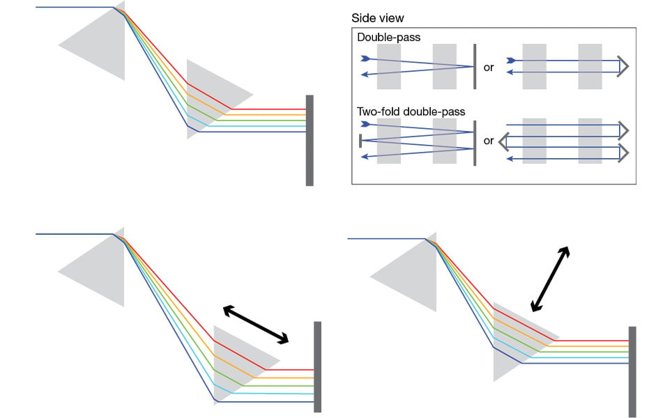
(Fine) adjustment of the amount of negative chirp is achieved by adjusting the position of the second prism (see lower panel of Figure 2). Both moving the prism along the optical axis (left) as well as changing how far the prism is inserted into the beam (right) will change the amount of GDD. The closer the two prisms are together and the thinner the prism section in the beam, the smaller the difference in wavelength-dependent delay. Both approaches can be found in commercially available prism pre-chirpers – with both having their own implementation challenges. No matter which is varied, the prism distance or the insertion of the second prism, the respective fixed parameter needs to be set up carefully initially, to ensure the best possible performance. If more negative chirp than can be achieved with a reasonable increase in the prism distance is needed, it is possible to reflect the beam back into the prism path for one or more further double passes (see inset in Figure 2).
Wavelength dependence
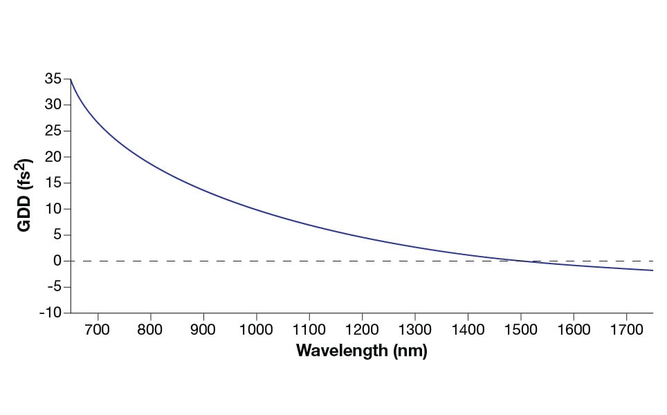
One final aspect to consider, is that dispersion is wavelength dependent. This dependence will vary with the material or combination of materials being used. Looking at GDD, generally the shorter the wavelength, the higher the dispersion (Figure 3). For the most common glass types, this means that the dispersion changes sign at longer wavelengths – switching from positively chirping to negatively chirping (i.e. shorter wavelengths travelling faster). This transition usually happens at some point between 1400 and 1700 nm. The result of this is that for three-photon microscopy different pre-chirping approaches will usually need to be used for imaging at 1300 nm (e.g. eGFP or GCaMP) and 1700 nm (e.g. m Cherry or R-GECO).
Higher Order Dispersion
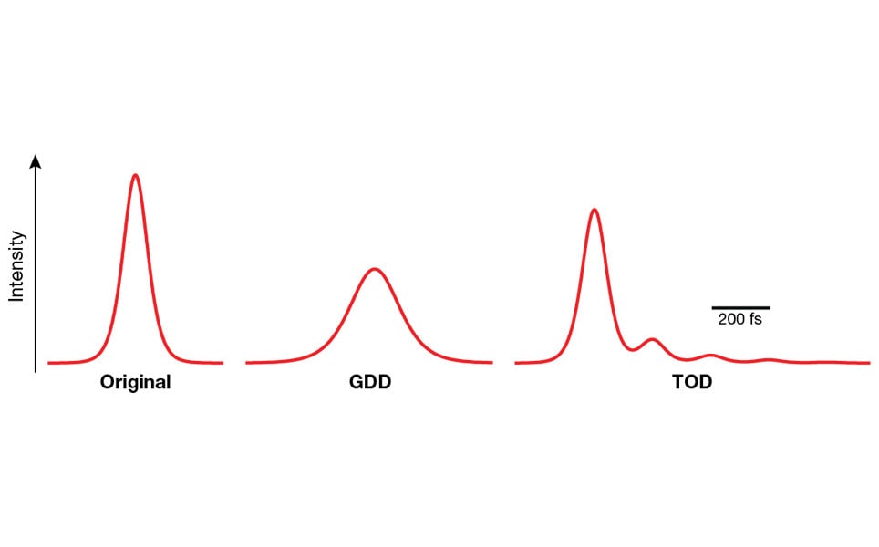
As pulse lengths shorten, the effects of GDD become more pronounced. At the same time, once pulses get into the 50 to 70 fs range, the impact of higher order derivatives of dispersion, so-called “higher order dispersion” become increasingly relevant. Here, the most dominant form is third-order dispersion (TOD). Both GDD and TOD lead to a decrease in peak power, but through different effects: GDD broadens pulses, symmetrically spreading the pulse energy over more time. In contrast, TOD causes energy to be moved from the core of the pulse, up to the point of creating something similar to satellite pulses (see Figure 4).
As pulse lengths shorten (below x fs), second-order dispersion has less impact on the pulse and higher-order derivatives become the dominant source of dispersion.
The concern here is that, in contrast to GDD, compensating for TOD is not straightforward. While the technology for compensating TOD exists, as of today suitable stand-alone commercial solutions for microscopy do not exist. This leaves avoidance of TOD as the only viable strategy for the time being.
Where does TOD arise? Just like GVD, it is a property of the optical materials that make up the microscope. As with GDD, this effect is more pronounced when using short pulses (anything above 70 fs tends to be of less concern). Unfortunately, in multiphoton microscopes the biggest source of TOD tends to be the prism-compressor used to compensate GDD. The larger the required GDD compensation range, the more TOD will be added. This is a result of the increasing amount of prism material that the pulses travel through in the course of the pre-chirping, but the geometric effect of the prisms on the beam also contributes.
Tying it all together
Current multiphoton microscopes tend to be substantially more dispersive than multiphoton microscope designs of the 2000 – 2010 era. This is a direct consequence of the increasing need for ever-wider spectral bandwidths (e.g. a wavelength coverage of at least 700 – 1700 nm has become typical), but also of the for larger fields of view, better field flatness and generally improved imaging performance. Achieving all of these requires increasingly more complex lenses, with more and more glass being added to the optical path, leading to more dispersive microscopes.
But this doesn’t mean that we need to accept broad and distorted pulses and the resulting loss of excitation efficiency. Careful selection and setup of the imaging equipment allows the use of pulses as short as 30 fs to be used without GDD or TOD becoming a limiting factor for imaging performance and quality of the resulting data.
One step to this is selecting components to avoid dispersion where it is not needed (e.g. replacing Pockels cells with other means of laser power control when using sub-70 fs pulses).
On the GDD-compensation side, the best performance is achieved when a prism compressor is designed or at least optimized for the intended experiments. This includes planning for the GDD of the microscope (including the table optics). More importantly, it requires the wavelength range and pulse width of the laser being used to be known and considered.
Finally, ensuring that the imaging equipment is set up well. This is particularly important for the prism compressor. The care taken here will have a major impact on the amount of TOD introduced at a given pre-chirping level. Adjusting the spacing of the prisms in a manner to minimize the amount of prism material required to achieve a given pre-chirp is key in avoiding unnecessary TOD.
As a closing thought, while there are instances where broader pulses can be better (a topic for yet another post), being able to fully compensate the GDD of your microscope while not introducing noticeable TOD is a key to unlocking the full potential of your multiphoton microscope.