

SciMethods: Controlling and Coordinating Experiments in Neurophysiology
Christian Wilms1
1 Scientifica Ltd, Uckfield, UK
Introduction
Most experiments in neurophysiology require multiple independent experimental components to be run in parallel. This can range from the recordings of electrical signals and timing of stimulation to the acquisition of fluorescence images or behavioural data. The timing of these different components must be known and reproducible to allow repeatable experiments and reliable data analysis. The standard method of achieving this is to use trigger signals. ‘Triggering an acquisition’ means that a data acquisition system (e.g. digitizer, camera, oscilloscope) is set up to wait for a predefined signal – the trigger – to occur before starting an acquisition. In the same manner, a stimulation system (e.g. electrical pulse generator, air puff, photostimulation, or a sensory stimulation system) can be set to generate a stimulation pattern only after a trigger is received. Figure 1 shows the schematic of a typical example, in which a hypothetical neuron is being recorded from continuously. However, only when a trigger is received is the data actually digitised and thus saved to disc. Synchronised with this train of acquisition triggers, a stimulator is triggered at a defined time point in each acquisition segment. The result is a series of traces with precisely timed stimulation. While this schematic experiment is a very simple example, it demonstrates the principle that can be applied to significantly more complex experiments.
Many different signals can be used as a trigger. The most common are digital outputs from a data acquisition system (e.g. a Molecular Devices DigiData) or a dedicated, stand-alone pulse generator (such as an AMPI Master-8 or an A-M Systems MultiStim). A ‘digital output’ is a brief, rectangular voltage pulse; typically stepping from 0 V to 5 V for a defined duration. Alternatively, dedicated equipment such as event detectors (e.g. a window discriminator) will allow threshold crossing or other criteria from a recorded voltage signal to be used as a trigger. As this technical note is intended as a basic introduction, we will focus on the former. When controlling an elaborate experiment containing multiple measurement and stimulation devices (e.g. electrophysiological amplifier, fluorescence imaging system, and optogenetic stimulation), there are commonly several approaches to ultimately achieving the desired outcome of a reproducibly timed experiment (see Figure 2). While sometimes these solutions are equally straightforward and effective, often this is not the case, and one will have significant advantages. Finding the best possible solution requires experience and a general understanding of the properties of the different systems. The aim of this technical note is to afford the readers this understanding, allowing them to then gain experience on their own. While we strive to provide sufficient background for a complete novice to follow the discussion, we do not provide detailed instructions on the usage of basic equipment such as oscilloscopes or electrophysiology equipment.
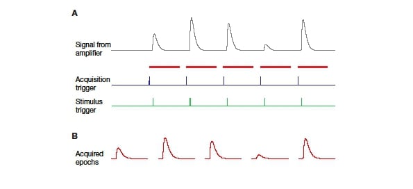
Figure 1: Schematic of basic triggering A: The amplifier records a continuous trace from the electrode (grey). The actual acquisition is triggered by an external signal (blue). Following the acquisition trigger, the digitizer (or other acquisition device) acquires the signal from the amplifier for a defined duration (indicated by red bars). Stimulation is triggered by a separate external signal (green) with a defined time shift to the acquisition trigger. B: The acquired signal resulting from the above scheme shows reliably timed responses to the stimulus. Many electrophysiology programmes refer to such repetitions as ‘epochs’.
Basic considerations
When running an experiment with multiple components, one of these will commonly act as a ‘conductor’, sending timing signals (triggers) at defined time points, while the others act as ‘players’, waiting for triggers to start the respective acquisition or stimulation. The sequence of acquisition and stimulation events, specifically their relative timing, define a physiological experiment. Such a predefined sequence of events is thus often referred to as a protocol.
In the simplest case, a recording system (e.g. an amplifier with a data acquisition module) sends a single trigger to a stimulator (Figure 2A), providing precise timing of the stimulation. Instead of directly triggering the stimulation, the recording system can also trigger a pulse generator that then sends a reproducibly timed stimulation pulse or pulse pattern to the stimulator (dashed line in Figure 2A). In most electrophysiology systems, the software paired with a data acquisition module (‘DAQ’) will function as a pulse generator, in addition to acquiring data (e.g. HEKA PatchMaster software paired with an EPC10 or Molecular Devices pClamp software paired with a DigiData).
The addition of further acquisition equipment (e.g. an imaging system) to this basic setup is straightforward: it is simply a matter of running a trigger line from the primary acquisition system to the new device. Next, the primary system is set up to send a trigger at the start of acquisition. The new device is then set up to wait for the trigger from the primary acquisition system. When the primary system triggers acquisition on the new device, both start simultaneously, so the datasets are synchronised (Figure 2B).
As mentioned above, once several pieces of equipment are involved, multiple solutions exist. As an example for this, the same devices used in the previous example (Figure 2B) can be arranged very differently: The imaging system could trigger the whole experiment, with the pulse generator timing the stimulation (Figure 2C). As pulse generators commonly have multiple independent output channels, the pulse generator could also control everything, starting the acquisition of both electrophysiology and imaging, while independently timing the stimulation pulses (Figure 2D). Several other combinations are conceivable as well.
The last three examples (Figure 2BCD) ultimately all achieve the same result. How does one decide which to use? The central factor to consider for this will be the flexibility in setting up protocols offered by the different equipment. Ideally, the most versatile device will control the whole experiment. Traditionally this would be a standalone pulse generator (e.g. Master 8), but more commonly today versatile software is used to setup the experiment timing and trigger external devices via the digitizer. A third alternative is to use a low-cost data acquisition module (e.g. National Instruments DAQs) combined with either freely available or in-house written software to replicate or even improve upon the functionality of a pulse generator. In any case, it is essential that the device controlling the experiment has sufficient timing accuracy for the intended work.
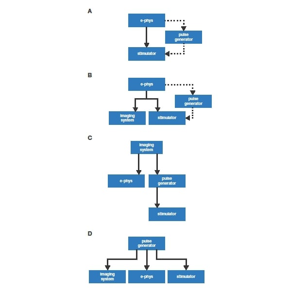
Figure 2: Different schemes for controlling a physiological recording. Solid lines indicate trigger lines. Dashed lines indicate optional additional trigger lines. A detailed discussion is provided in the main text.
Implementation examples
We discuss three examples of triggering solutions in further detail. The examples are listed in order of increasing complexity. While they differ in their simplicity and performance, all three (electrophysiology suites, general purpose data acquisition hardware, and microcontroller-based approaches) can provide very reliable and accurate experimental timing. Nonetheless, it is possible to create substantial confusion with all of these options as well. It is thus strongly recommended that before running a full experiment, the timing of the trigger signals be verified (see below for details).
Using an existing electrophysiology system
For measurement rigs already equipped with a dedicated electrophysiology system, it is logical to leverage the fact that a high quality, versatile DAQ is already present. In addition, most of these packages include a powerful protocol editor, making it easy for the user to set up experiment timing.
To allow the electrophysiology system to control an experiment, the digital outputs of the electrophysiology digitizer are connected to the trigger inputs on the other devices. Now, using the protocol editor of the electrophysiology software, digital pulse patterns can be defined that activate the additional devices as desired.
One of the advantages of this approach is that it comes for free if a suitable electrophysiology system is already present. Another is the ease with which complicated experiments can be set up, as defining digital pulse patterns is straightforward. Within a single pattern, the timing of pulses is extremely accurate, with a variable time base well below 1 ms; as determined by the sampling frequency.
The disadvantage is that if such a system is not already present, it comes at a high cost. Furthermore, while modern electrophysiology software is normally quite versatile, the user is limited to the functions that are implemented by the manufacturer.
Using general purpose DAQ hardware and third party software
An alternative to a dedicated electrophysiology system is the use of general purpose data acquisition hardware. A wide selection of general purpose data acquisition devices (DAQs) are available from numerous manufacturers. The most significant advantage of such DAQ hardware is that it is available at significantly lower prices than dedicated electrophysiology DAQs. The DAQ hardware most commonly used in neuroscience is produced by National Instruments (www.ni.com). NI provide a selection ranging from very basic modules for around £100 to sophisticated integrated solutions at significantly higher costs. Depending on the required timing precision and additional required functionality, reliable experimental control can be achieved with NI modules for well under £1000.
Similar to the dedicated solutions discussed above, general DAQ hardware is controlled by a computer. In contrast to pure electrophysiology solutions, general purpose DAQs are not provided with a software dedicated to typical neuroscience experiments. Instead, a selection of third-party software written for such DAQs is available for neuroscience or general physiological applications. Some of these software packages are written to work with DAQ hardware from multiple manufacturers, while others are hardcoded to work with DAQs from just one manufacturer. All of the software packages we have found used in neuroscience labs support NI hardware. Interestingly, some of them also support outdated dedicated electrophysiology DAQs (e.g. Digidata 1200 and older ITC or CED modules). Such older hardware can often be found lying forgotten in departmental cupboards and be given a new lease of life with modern third-party software.
As above, for any of these hardware/software combinations, the respective outputs from the module must be connected to the trigger inputs of the equipment which is to be controlled. The specifics of this will differ depending on the DAQ hardware used.
Out of the large selection of third-party software, we have chosen two examples to highlight. WinWCP, written by Dr. John Dempster (University of Strathclyde; spider.science.strath.ac.uk/sipbs/software_ses.htm) and PackIO1, written by Adam Packer (University College London; packio.org). The former is a dedicated patch-clamp software with support for a wide range of different DAQ manufacturers. PackIO, on the other hand, is a general input/output package that includes some modules for electrophysiology that only works with NI hardware. Both of these programs include advanced protocol editors, making them well suited for controlling complex experimental flows requiring the synchronisation of multiple pieces of equipment.
WinWCP is a fully developed patch-clamp software, with functionality resembling commercial electrophysiology suites (e.g. pClamp, Axograph or PatchMaster). Inputs and outputs are defined based on the specific DAQ module used. The protocol editor will allow the setup of complex pulse patterns that can also be triggered by an external device. Especially when using lower specification DAQ modules such as the NI USB-6000 series, it is vital to ensure that the pulse timing is indeed as expected. When using dedicated electrophysiology DAQ modules, this is of less concern.
In contrast to WinWCP, PackIO is not targeted specifically to electrophysiology, but rather makes the power of NI DAQ devices easy to access for any type of data input and output. In this capacity, it provides a full-featured protocol editor, that allows well-timed signalling to downstream equipment. While PackIO allows the digital outputs of NI modules to be used, in practice it is recommended to use analogue outputs to generate 5 V pulses, as these are hardware-timed (i.e. timed by the actual DAQ module), guaranteeing precise timing. In contrast, software-timing, where the PC controls the timing, is less reliable as it depends on the operating system’s scheduler. The documentation of the respective DAQ module will provide details on hardware timing of different ports.
In combination with a compatible DAQ both of the above programs can also be used for electrophysiology experiments, offering a low-cost entry to this field.
While this Application Note is aimed at beginning neuroscience researchers, it still should be mentioned that it is reasonably easy to write your own software to control general purpose DAQs. Especially National Instruments hardware is supported by the most common programming and data analysis environments (LabVIEW, MATLAB, Igor Pro and, with some limits, Python). For most users, the existing solutions will be sufficient, but for some specialised cases writing your own software may well be the best option.
Using an Arduino/Genuino microprocessor
In recent years, user-friendly microcontroller boards have become very common in physiological laboratories. They can offer quick and easy solutions to a wide range of problems that not so long ago would have required expensive equipment to address. The most commonly used microcontroller module is the Arduino (www.arduino.cc; due to legal issues now available as Genuino outside of the USA). While we will refer specifically to Arduino-based solutions here, similar results can be achieved with other microcontroller-based platforms.
Currently, no ready-made solutions for experimental control using Arduinos are available. Thus, this approach requires programming by the user. This programming is commonly done in the Arduino IDE in a variant of the C programming language known as ‘Wiring’.
Arduinos, similar to most microcontrollers, are equipped with a selection of pins that can act as both inputs and outputs. The majority of these pins are dedicated to digital input/output (I/O) only, while a few pins are intended to be used for analogue input, but can be repurposed for digital I/O as well. A digital pin can have two states: ‘LOW’ (off; 0 V) or ‘HIGH’ (on; 3.3 or 5 V, depending on the specific board used). At the beginning of an Arduino program (called ‘Sketch’), the pins that will be used in a project are assigned a mode as input or output. It is now possible to read from input pins using the ‘digitalRead’ function and write to output pins using the ‘digitalWrite’ function. In addition, there are a series of functions to deal with timing. Outputting a trigger signal is as easy as setting an output pin to HIGH, waiting for a few milliseconds (e.g. 10) and setting the pin back to LOW:
digitalWrite(OutputPin,HIGH); delay(10); digitalWrite(OutputPin,LOW);
Complete tutorials are available on www.arduino.cc as well as many other websites.
A word of caution on timing pulses is needed. The ‘delay’ function as used in the above example is unsuited for setting precise timing, as the duration of other computations running between the delay statements are not taken into consideration. An example of how to set timing more reliably is provided here: http://www.arduino.cc/en/Tutorial/BlinkWithoutDelay.
Connecting the Arduino board to other equipment can be achieved using simple 0.1” plugs commonly used in electronics. While this is quickly done and requires only small amounts of soldering to make a connection to a BNC socket, it is also quite error prone. More recommendable is to mount the Arduino in a project box (‘prototype box’ or ‘prot box’ for short), install the required number of BNC sockets on the outside of the box, and connect the pins to the inside of these sockets. The result is a much more reliable piece of kit that can be easily transported to other equipment. It is also straightforward to add buttons, LEDs or LCD displays to this box, allowing for additional communication with the Arduino and creating a unique and potentially very useful tool.
General recommendations and conclusions
As mentioned above, it is important that before running a valuable experiment the setup of the experiment timing is verified. This can be done either using an oscilloscope or by acquiring the relevant trigger signals with a data acquisition system by feeding them into separate analogue input channels. For many stimulation modes it is straightforward to register the actual stimulus, which is more useful for verifying the timing than the corresponding trigger signal: In the case of visual stimuli, a photodiode can be used to detect the stimulus timing. Air puffs can be detected using a piezo transducer or a simple microphone. The same holds for acoustic stimulation as well as vibration.
It is a good idea to critically consider what level of timing accuracy is required for the planned work. Most physiology experiments will not need timing accuracy below 0.1 ms. Thus, using equipment capable of single microsecond timing accuracy makes little sense. Planning for this can potentially save costs and simplify the experiment layout, as well as later analysis.
Another point to consider is how trial repetitions will be handled. If each repetition is acquired independently, the repetitions probably do not need to be hardware timed relative to each other. In this case, small timing errors might also be acceptable, as they do not add up. On the other hand, if trials are repeated many times in a single acquisition, timing errors can add up, potentially leading to larger errors over the course of a long recording.
In the case of very long acquisitions with multiple repetitions of possibly varying stimuli, it makes sense not to rely solely on experimental control for synchronisation. In such cases, it is recommendable to record the timing of stimuli and trigger signals in parallel to the raw data. For this, the strategies to detect stimulus timing mentioned above can be easily adapted. In addition, routeing and acquisition signals such as frame timing from cameras or scan signals from laser-scanning microscopes can also be recorded. Such an approach makes it easy to align multiple streams of parallel acquired data during analysis, allowing straightforward automation of data analysis.
As laid out in the beginning, experiment control is of central importance to physiological research. While there are some common principles, details on how to set up the intended experiment in a stable and reliably timed manner will differ from application to application. Here, we have presented a series of basic principles which we hope will help new researchers get started in designing their own experiments efficiently.
Endnotes
1. Watson, B. O., Yuste, R. & Packer, A. M. PackIO and EphysViewer: software tools for acquisition and analysis of neuroscience data. bioRxiv (Cold Spring Harbor Labs Journals, 2016). doi: 10.1101/054080
We thank James Rowland and Adam Packer for helpful input and discussions on the manuscript.
Read more SciMethods
- Using a Scientifica Multiphoton SliceScope for Fluorescence Lifetime Imaging
- Paired Blind Polytrode and Juxtacellular Recordings In Vivo
- Simultaneously recording from four neurons using PatchStar and MicroStar manipulators
- Visual Stimulation of Retinal Explants on a Standard Multiphoton Microscope
Sign up to receive our latest news
Find out about Scientifica's latest product releases, company news, and developments through a range of news articles, customer interviews and product demonstration videos.