

Understanding the cell as an electrical circuit
Lea Goetz1 and Christian Wilms2
1UCL, London, UK
2Scientifica Ltd, Uckfield, UK
Electrophysiologists frequently describe cells as electrical equivalent circuits, i.e. a combination of resistors and capacitances. In the following article, we will look at how resistance and capacitance determine the electrical properties of the cell to understand why this is a useful description.
Membrane resistance, RM
The cell membrane consists of a double lipid layer that separates ions in the extracellular space from ions and charged proteins in the cytoplasm. While pure lipid membranes are excellent electrical insulators, real cell membranes consist of a dense mosaic of proteins and lipids. Many of these proteins span the membrane and act as channels that allow charge to pass. These proteins reduce the otherwise high resistance of the membrane, which has significant consequences for electrophysiology. Assume we want to apply a voltage across the cell membrane by injecting current with an electrode. The current required to maintain this voltage is determined by the membrane resistance, according to Ohm's Law: Voltage = Resistance * Current (or V = R * I). We can see that the higher the membrane resistance, the lower the current required to maintain a given membrane voltage.
Membrane capacitance, CM
Because the membrane is an electrical insulator separating opposing charges inside and outside the cell, the cell membrane not only has a resistance but also a membrane capacitance. Therefore, to change the membrane voltage, it is necessary to charge the capacitance. The applied charge (Q) divided by the membrane capacitance (CM) gives the membrane voltage (Vm): Vm = Q /CM. We can see that for a given amount of applied charge, the smaller the membrane capacitance, the larger the membrane voltage change.
Combining RM and CM – the RC circuit
As both the membrane resistance (RM) and the membrane capacitance (CM) occur over the cell membrane, they are electrically parallel (see Figure 1A). Such a circuit of parallel resistance (R) and capacitance (C) is known as an RC circuit. RC circuits are commonly used in electronics as basic filters to select particular input frequency ranges. Similarly, the cell membrane acts as a filter on current or voltage injected into the cell.

Figure 1. Basic schematic of the electrical properties of a plasma membrane. A: A circuit diagram showing the membrane capacitance and membrane resistance in parallel to each other. B: Traces showing a command voltage step (top) and the resulting current response (bottom) for a simple plasma membrane being voltage clamped.
Basic voltage clamp experiment
To understand how the RC filter properties of the membrane determine a cell’s voltage response, consider how a voltage step applied to the inside of a cell alters the current injected through an electrode (see Figure 1B). Initially, a square shaped voltage step leads to an instantaneous jump in current (the initial peak). This current then decreases exponentially (falling flank) to reach a steady state. Contrary, when the voltage step is reversed, we observe a large instantaneous current of the opposite direction that decreases exponentially until it reaches steady state again. Controlling the membrane voltage and measuring the resulting current in this way constitutes a basic voltage clamp experiment.
How do the properties of the electrode and cell membrane influence the shape of the current curve (see Figure 1B)? Initially, the entire current charges the membrane capacitance with no current flowing across the membrane resistance. Thus, the amplitude of the initial fast current is entirely determined by the size of the voltage step and the electrode resistance (which is defined as the sum of the resistance of the electrode and the resistance of the electrode’s connection to the cell). As the membrane capacitance becomes more and more charged, an increasing fraction of the injected current flows across the membrane resistance. Once the capacitance is fully charged the system reaches a steady state and the entire current flows across the resistors - namely the membrane resistance and the series resistance collectively known as the input resistance. In the steady state, the
amount of current required to maintain the membrane voltage is only determined
by the input resistance and Ohm's law applies (steady state current = Voltage step/Rs+Rm. I.e. the total (or input) resistance.
Determining the state of a recording
We can use the above relationships to monitor various stages of a whole cell recording. To do so, we apply a small voltage pulse at the electrode, the so-called test pulse. By observing the shape and amplitude of the current response to the test pulse (Figure 2, right column), we gain lots of useful information about the recording electrode and the cell. Importantly, many of the concepts apply to other forms of electrophysiological recording as well.
To assess the state of our recording we make simple calculations based on rearrangements of Ohm’s law (V = R * I). It is possible to simplify the calculations further by using resistance in units of MOhm (106 Ohm), voltage in units of mV (10-3 V) and current in units of nA (10-9 A), as the unit prefixes, cancel each other (10-3 V = 106 Ohm * 10-9 A).

Figure 2. Schematic explaining the ‘pipette in bath’ configuration. In this configuration, the current is determined solely by the pipette resistance. The pipette is indicated on the left. The corresponding electrical circuit is shown in the middle with the voltage and current traces depicted on the right.
Recording electrode in the bath
Entering the bath is the first stage in a recording: the recording electrode, which is inside a pipette filled with internal solution, is submerged in the perfusion media (Figure 2). By definition, the voltage between the recording electrode and the reference electrode is zero. Accordingly, the amplifier’s offset voltage needs to be adjusted until the measured voltage is indeed 0 mV.
With the pipette in the bath, the current response to the test pulse is determined by the pipette resistance (RP), which can be calculated using Ohm’s law: RP = VT / IP, where VT is the amplitude of the voltage test pulse and IP is the current through the pipette. For example, a -5 mV test pulse yields a current response of -500 pA. This indicates a pipette tip resistance of 10 MOhm (= -5 mv / 0.5 nA). In whole cell recordings, it is common to use pipettes with tip resistances of 5-10 MOhm.
Approaching a cell and forming a seal
When approaching a cell with a pipette, one applies positive pressure to the internal solution, to prevent tissue from obstructing the pipette tip. Despite this precaution, the amplitude of the current response to the test pulse will vary during the approach: when the pipette tip touches tissue, the resistance will increase, leading to a drop in the current amplitude. Slightly retracting the pipette should return the current response (as a consequence of the pipette resistance) back to the initial value. However, these changes are relatively small and transient.
Once the pipette comes very close to a cell, the amplitude of the test pulse decreases which signals a marked increase in electrode resistance. This usually coincides with the formation of a dimple on the cell surface, where internal solution expelled from the pipette tip pushes away the cell membrane. Removing the pressure from the pipette at this point allows the cell membrane can contact the pipette yielding a substantial increase in electrode resistance. Applying mild suction to the electrode’s internal solution increases the resistance further. At this stage, a negative command voltage (roughly matching the expected intracellular potential of -60 mV to -80 mV, depending on cell type) is applied to the pipette. Analogous to the test pulse, the current response to the holding voltage can be used to determine the state of the recording, as the holding voltage, and the required holding current, are linked to the pipette resistance. So, if -200 pA is needed to hold the pipette at -60 mV, the pipette resistance is 300 MOhm (= -60 mV / -0.2 nA).
On-cell configuration
At this point, it is important to consider how the current from the pipette flows to the ground electrode. As the small patch of cell membrane in the pipette tip has a very high resistance, any current flowing from the pipette will be flowing through the minute gap where the membrane seals onto the glass of the pipette. Accordingly, the measured resistance is determined by the resistance of this 'seal', unsurprisingly referred to as seal resistance. Reliable patch-clamp experiments commonly require a ‘tight seal’ in the range of GOhms, a so-called ‘gigaseal’. We can observe that a tight seal has been achieved when the current required to hold the pipette at -60 mV is smaller than 60 pA (-60 mV / -0.06 nA = 1 GOhm). This state is known as the ‘on-cell configuration’ (Figure 3).
In the on-cell configuration, the current response often shows a very fast spike at the onset of voltage steps. These are caused by the pipette capacitance and can be compensated using the ‘fast capacitance compensation’ available on most amplifiers. Especially if you are interested in fast ionic currents, it is important to carefully compensate the pipette capacitance as much as possible.
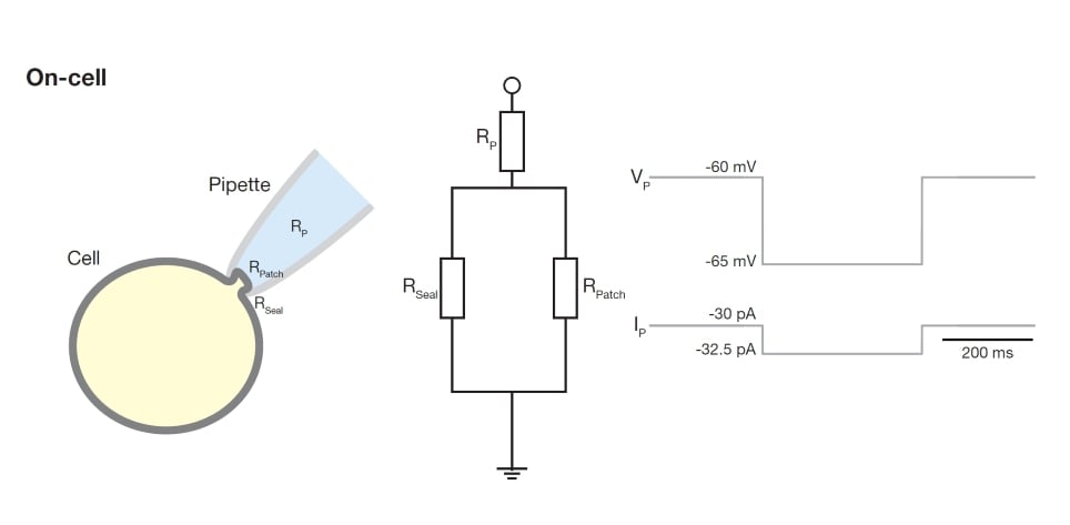
Figure 3. Schematic explaining the ‘on-cell’ configuration. In this configuration, the current is determined by the pipette resistance in series to a parallel circuit of the patch and seal resistances. The pipette with cell is indicated on the left. The corresponding electrical circuit is shown in the middle with the voltage and current traces depicted on the right. Note that as the patch resistance is very high, the current over this resistance is negligible.
Scientifica PatchStar Micromanipulator
The most versatile motorised manipulator for electrophysiological studies. Designed with leading physiologists, the PatchStar is ultra-stable, with less than 1 µm drift over 2 hours for long-term experiments. It is electrically quiet for recording of extremely small signals without having to switch off the motors.
Whole-cell configuration
Once a tight seal has formed, we can gain electrical and diffusional access to the cell’s cytoplasm by rupturing the membrane under the pipette tip while maintaining the obtained seal. This process is often referred to as ‘breaking into the cell’, and the resulting recording configuration is known as ‘whole-cell’. In this configuration, the recording pipette is electrically directly coupled to the cell: the electrode can ‘see’ the electrical activity inside the cell. As a result, the current response to a given voltage pulse changes dramatically, as does the information that this response provides (Figure 4).
On breaking into the cell, the membrane in the pipette tip ruptures and current between the recording electrode and the ground can now flow into the cell and across the cell membrane. In this whole-cell configuration, almost all current flows across the cell membrane and charges the membrane capacitance. Only a negligible amount of current will flow across the seal, as the seal resistance is at least an order of magnitude larger than the membrane resistance (now, the membrane resistance is determined by the entire cell’s membrane area, not just the membrane patch within the pipette tip). Because the membrane is ruptured and not removed, membrane components will obstruct current access from the electrode to the cell and contribute a so-called 'access resistance'. The sum of access resistance and initial pipette resistance make up the total resistance at the pipette tip, referred to as series resistance. In practice, only the total series resistance is known.
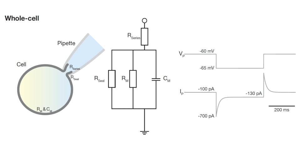
Figure 4. Schematic explaining the ‘whole-cell’ configuration. In this configuration, the current is determined by the series resistance in series with a parallel circuit of the seal and membrane resistances as well as the membrane capacitance. The pipette with cell is indicated on the left. The corresponding electrical circuit is shown in the middle with the voltage and current traces depicted on the right.
Current response in whole-cell configuration
Looking at the current response to a voltage step, it is straightforward to pick apart which electrical properties contribute to which bit of the response (see Figure 4). As before, the fast initial jump in current is determined by the flow of charge through the pipette: series resistance (Rs) = test voltage (VT) / initial current (IP). Thus, if in response to a -5 mV step, the initial current is measured as -600 pA, the series resistance is 8.3 MOhm (-5 mV / -0.6 nA). The decay of the current is determined by the voltage-clamp time constant (Vtau), which shows how fast the cell changes its voltage in response to a current step delivered through the pipette. Having measured the resistance and fitted the currents decay, it is possible to calculate the cell's membrane capacitance (Cm = Vtau / Rs). Finally, once the current has reached a steady state, the offset current (‘holding current’, IH) is determined by the input resistance (Ri = VT / IH). Having measured the membrane resistance, it is in principle possible to determine the membrane time constant by fitting the exponential decay of the current and calculating the membrane capacitance (Cm = tm / VT).
Theory vs. Practice
In passive and compact cells, a single capacitance and resistor are sufficient to describe the electrical behaviour of the cell, allowing for all the calculations described above. In practice though, neurons are large extended membrane structures, and their membranes are not passive but contain voltage-dependent ion channels. Thus, when performing electrophysiological recordings, it is important to keep in mind where the reality of neuronal physiology deviates from the ideas presented above.
The good news is that up to and including the formation of a tight seal in on-cell mode, all the assumptions described above hold true. The bad news is that much work is done in whole-cell mode, at which point practice deviates from theory and things become more complicated.
One key point to consider is that the voltage pulses used to assess the state of the recording can activate voltage-dependent conductances. Consequently, the steady state current can contain current components that are not related to the membrane resistance but stem from voltage-gated ion channels, such as the hyperpolarization induced current IH.
Furthermore, in larger cells with a more complex morphology, multiple sets of parallel resistors and capacitances are required for an accurate description of the electrical properties of the cell. As a rule of thumb, the farther from the pipette tip a cell compartment is, the more its voltage deviates from the voltage applied through the electrode, the so-called 'space clamp' problem.
A full discussion of the reality of single cell recordings is beyond the scope of this article, and we refer the reader to the standard literature on the topic.
Recommended reading:
“Foundations of Cellular Neurophysiology”
Daniel Johnston and Samuel Miao-Sin Wu
“Single Channel Recording” 2nd Edition Edited by Bert Sakmann and Erwin Neher
“Axon Guide” Molecular Devices
Thanks to Dr Christian Wilms and Nour Al-muhtasib for their help with this article.
)