

A guide to stitching images using Micro-Manager and ImageJ
You have completed your experiments and acquired your data. Now, all you need to do is take an image of the whole slice to show exactly where you are patching from. How are you going to do this? Take pictures of the brain slice while manually moving the stage, to later use Paint and put those pictures together by eye?
There are better ways of doing this. In this article, we will guide you through how to use Micro-Manager to acquire XY images with a Scientifica stage, then put the images together using FIJI.
Acquiring a series of images and stitching them together using FIJI
Setting up the Micro-Manager configuration file
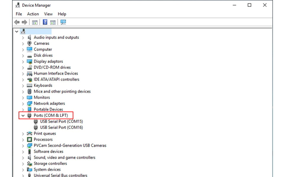
Functions in Micro-Manager that have control of the XY stage will require this to be added to the configuration file in use. The COM port number of the motion control card driving the XY stage is required for this. To check this, open Windows Device Manager and check under ports (COM & LPT), (see figure 1). You can find which COM port belongs to the stage by unplugging the USB cable of the stage controller, making a note of which COM port disappeared, then plugging it in again to double-check.
In the Micro-Manager software, select 'Tools' and then 'Configuration Wizard' (Figure 2).
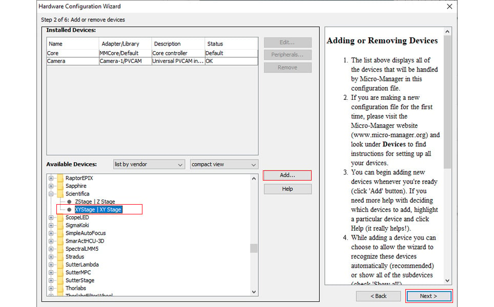
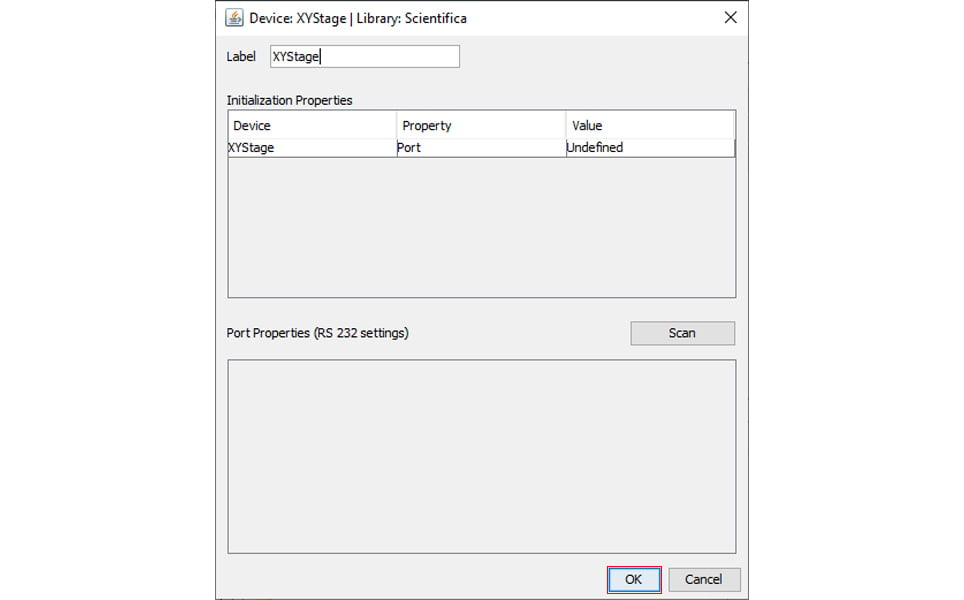
Add the XY stage. In the following window, click on 'Undefined' and enter the COM port number identified above from the drop-down list that appears, then click ‘OK’ (Figure 3).
Click on ‘Next’ through the following sequence of windows and follow on-screen instructions to finally save this new configuration file. This is the configuration file that should be loaded on startup of Micro-Manager to use this software to control the XY stage. You can always add another device in a similar way during this stage, such as cameras and shutters. Micro-manager has an extensive list of devices they support.
Warning if you are using LinLab2: it cannot be operated at the same time as Micro-Manager in this configuration, because the control of COM ports cannot be shared.
Calibrating Micro-Manager Tile Creator
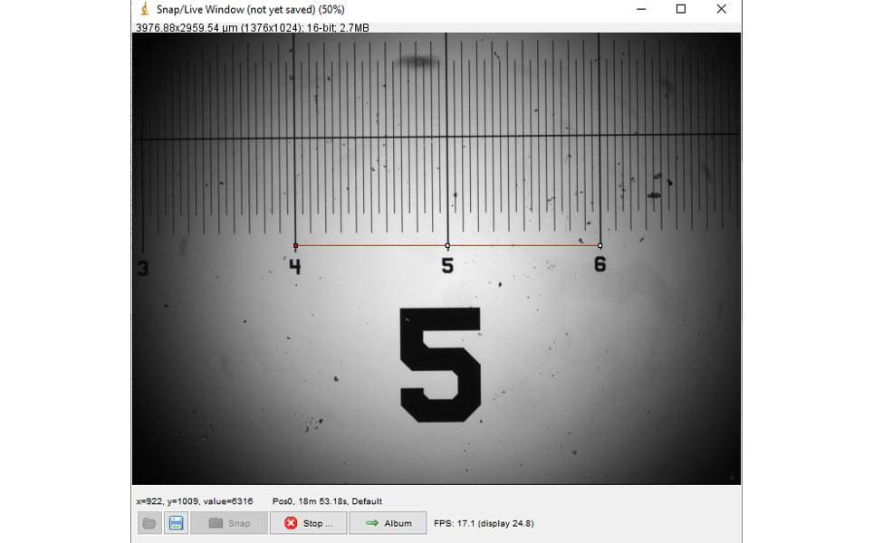
Tile Creator requires you to enter the pixel size (in micrometres, μm, in this case). Pixel size can be determined by using the line tool in FIJI to draw a line of known distance between two points on a calibration rule (Figure 4).
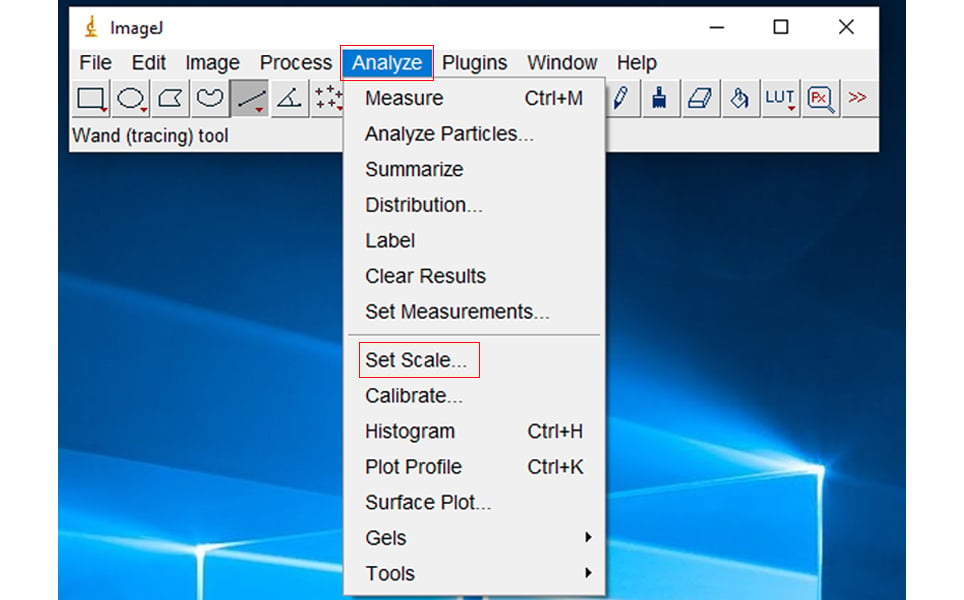
Select 'Analyse', followed by 'Set Scale' (Figure 5).
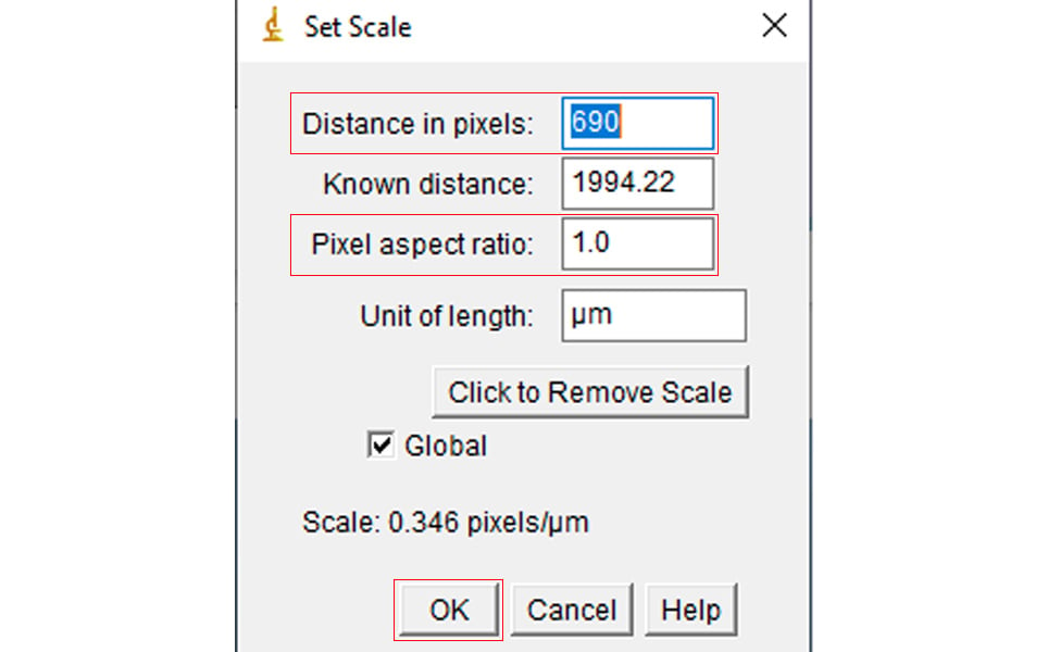
The length of the line is displayed in pixels. Enter the known distance (Figure 6). Refer to the Set Scale window to check the current pixel to μm ratio.
Using Tile Creator
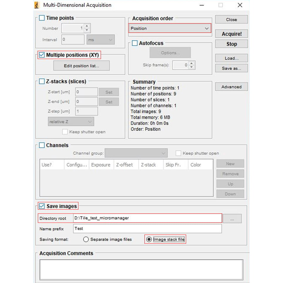
In Micro-Manager, select 'Multi-Dimensional Acquisition' (Figure 7). Check ‘Multiple positions (XY)’. If you have more than one channel and more than one time point to record, you should check ‘Time points’ and ‘Channels’. You will have different ‘Acquisition order’ options. The position is the important one at the moment.
Images are saved to the disk in the ‘Directory root’ set up under ‘Save images’ in the Multi-Dimensional Acquisition window. For simplicity, select the ‘Save format: Image stack file’ option. The other option is not particularly useful if you are taking a lot of images or require faster acquisition.
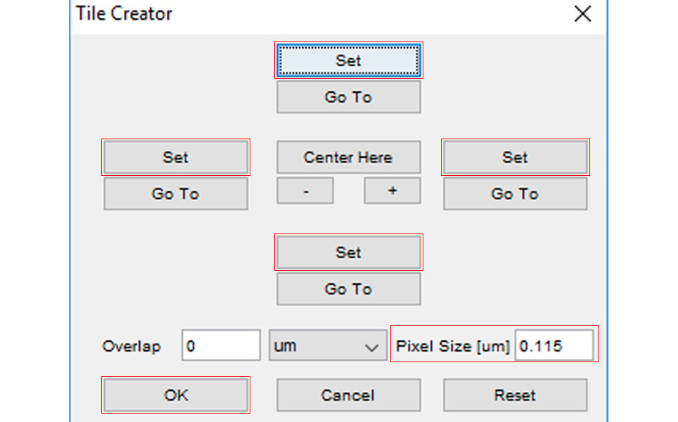
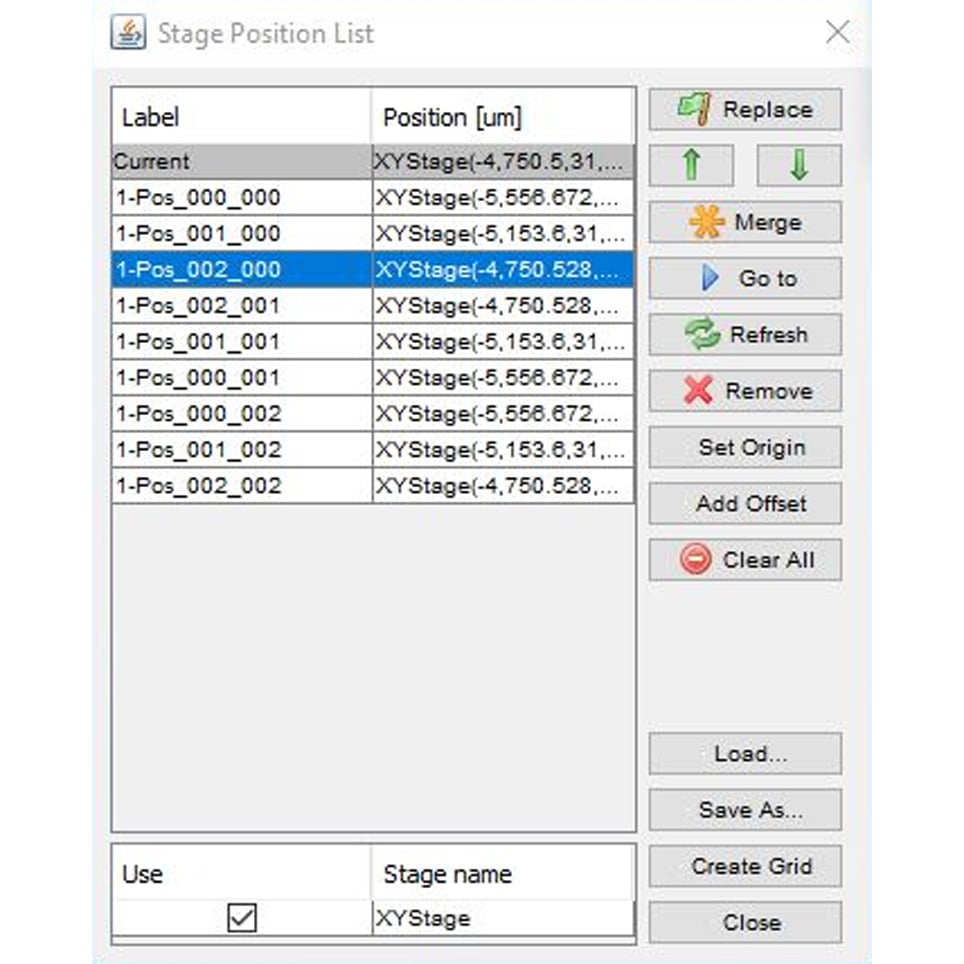
Under 'Multiple positions (XY)', click on ‘Edit position list…’. You will see a blank list on a window called ‘Stage Position List’. Click on ‘Create Grid’ to open Tile Creator (Figure 8).
Enter the pixel size as determined above in ‘Calibrating Micro-Manager Tile Creator’. Overlap can be set as a percentage - 10-20% normally works well.
Move the stage (using the PatchPad or Control Cube) to the top left corner of the area to be imaged and click on the upper and left hand ‘Set’ buttons.
Move the stage to the bottom right corner of the area to be imaged and click on the bottom and right hand ‘Set’ buttons.
Alternatively, you could set up the view you are at as the centre, and Micro-Manager will take another 8 pictures surrounding that centre (in a 3x3 frame).
Click OK.
A list of calculated positions will appear in the stage position list (Figure 9). In the ‘Multi-Dimensional Acquisition’ window click ‘Acquire’. The stage moves to the calculated positions and images are stored at each position of the list.
Stitching acquired images in FIJI
Using FIJI (if you are using ImageJ you probably need to download the plugin for this), go to 'Plugins --> Stitching --> Grid/Collection stitching'.
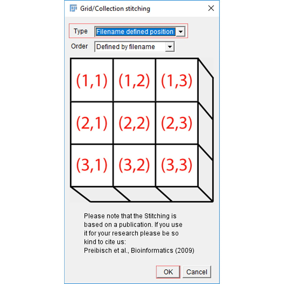
In the Grid/Collection stitching window, select ‘Type --> Filename defined position’. The files created by Micro-Manager have a specific setting that shows x, y and z positions when acquired.
Click ‘OK’.
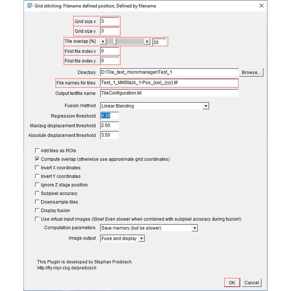
In the following window, input both ‘grid size x’ and ‘grid size y’. The ‘Tile overlap’ is normally fine at 20%, but you may need to change some numbers in order to get the desired image.
Change the ‘First file index x’ and ‘First file index y’ to 0. Then select the directory that you stored the files in.
The ‘Files names for tiles’ should contain the general name for the files you created. If you haven’t changed anything from the Tile Creator, the names of the files should be in this format: img_n_MMStack_n-Pos_{xxx}_{yyy}.ome.tif.
Some explanation:
The “img” part corresponds to the name you’ve used for the Micro-Manager (in our case, Test), “n” is the number of the image group (starting with 1).
To define the position in x and y, you need to put between curly brackets - {} - which one is x and which is y. These will be the iterations that the plugin will go through in order to make the stitched image, starting from 000. So in our example, it will be Test_1_MMStack_1-Pos_{xxx}_{yyy}.ome.tif.
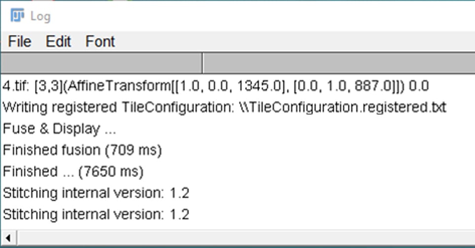
When you click on ‘OK’, a log will be produced (which may indicate where errors have occurred), along with a tile configuration register and a fused image (Figure 12).
Please note: Sometimes the result will be only the first image you have copied over and over again in each of the position on the grid. This can be avoided by renaming the image files and only deleting the .ome final part of the file. It seems that this can cause some confusion with the stitching plugin.
It is also important to ensure that you have to put the file name extensions. If you don’t, the plugin won’t find the files.
Sign up to receive our latest news
Find out about Scientifica's latest product releases, company news, and developments through a range of news articles, customer interviews and product demonstration videos.